
Home
Shop
Tools
Empennage
Wings
Wings 2
Left Wing
Gretz Pitot Install
Left Tank
TruTrak Roll Servo
Capacitive Senders
Closing Left Wing
Wings 3
Wings 4
Fuselage
Panel
Firewall Forward
Canopy
Wiring
Miscellaneous
Wings 2
|
Date |
Description of Task | Hours |
| Left Wing | ||
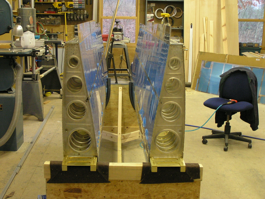
| 10/20/06 | Today I started by setting up the right wing on
the stand and clamped it down. I decided to build up the
left wing and then with it on the cradle I can work on the
ailerons and flaps for both wings simultaneously. Since
this is mostly a repeat of the steps with the right wing I will
not be posting as many pictures. I will have pictures of
new issues as they present.
|
1.0 |
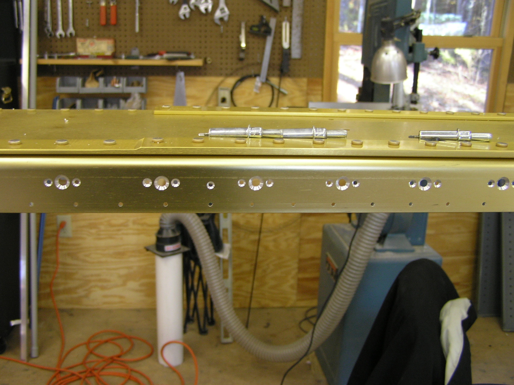
| 10/21/06 | I drilled the spar to #40 for all the 124
platenut rivets as well as all the other flange rivets top and
bottom. Then I countersunk the rivets. I then dabbed the
countersinks with Alodine using a Q-tip. I began riveting
the #8 platenuts. I started countersinking the
platenut hole for the #8 screw. I used a cut-off #8 screw to gauge the countersink depth.
|
3.0 |
| 10/22/06 | Finished countersinking the spar for the #8
screws...all 62 of them. Alodined each countersink.
I also riveted the #6 platenuts for the inspection covers.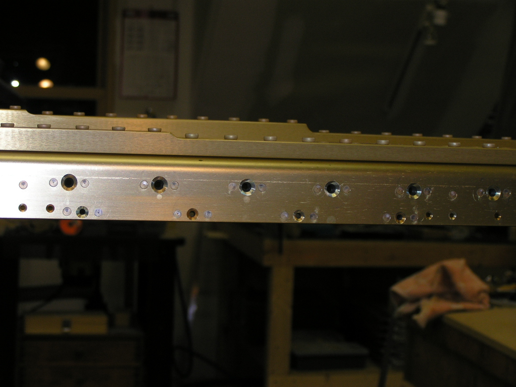
Drilled and riveted the two center section platenuts on the
spar. Drilled the tie-down bar to the spar and attached
the four platenuts and primed using the rattle can. Bolted
the tie-down and torqued to 25 in/lbs. Began working on the left wing rear spar.
Drilled and clecoed the W-907D and W-907E doubler plates to the
spar. Drilled the hole for the aileron pushrod using my
Unibit then cleaned it up with my Dremel tool. Took
the whole assembly apart and deburred the spar and doubler
plates. The rear spar is ready to chemically treat
with SanChem.
|
5.0 |
| 10/27/06 | Using the SanChem, I chemically treated the rear
spar and doubler plates. After drying, I countersunk the
holes in the rear spar where needed. I used alodine to
spot-treat the countersunk holes and riveted the rear spar
assembly. I saved myself
some time and just referenced
Smitty's website to determine which holes received rivets
and which shouldn't. Next, I placed the main spar and rear
spar on the table and clecoed the ribs to the spars. You
have to pay attention to the plans to arrange the ribs in the
proper orientation. I was really proud when I had finished
to find that I had NO left-over ribs :) |
3.0 |
| 10/29/06 | Match drilled the main ribs to the front and
rear spars. Disassembled the ribs and set aside for
chemical treating.
|
1.0 |
| 11/3/06 | Scotchbrite scrubbed all 15 main ribs with soap
and water.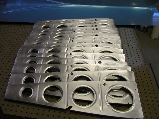
|
2.5 |
| 11/4/06 | Etched and chemically treated the main ribs.
Clecoed the main ribs to the main spar and riveted.
Clecoed the rear spar to the main ribs and riveted. Drilled the 1"x1" angle to the outboard rib and attached. Hung the left wing assembly on the wing stand. Drilled the wing walk doubler as per the plans. Clecoed the inboard skin, doubler and outboard top skin to the wing skeleton.
|
6.5 |
| 11/5/06 | Match drilled the inboard and outboard skins to
the ribs.
Cut, deburred and drilled the J-stringers to the top skins. 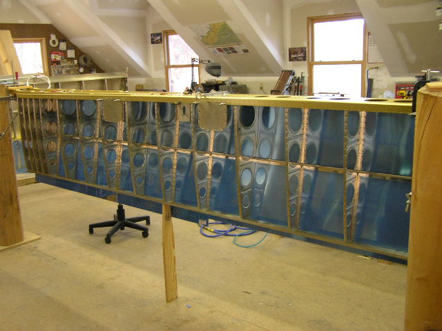
Gretz Pitot Install
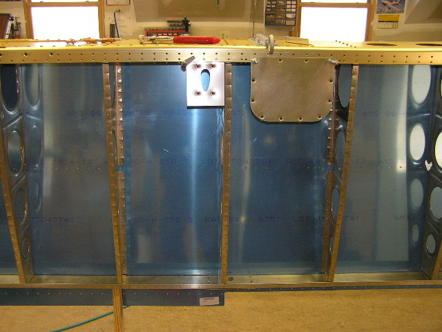
I am attempting to determine the best location for mounting my Gretz pitot. I basically have three options.
Option 1:
This is where Vans suggests installing the pitot and has
holes in the ribs to this bay for routing lines. I feel the
pitot head will be too close to the tie-down ring.
Option 2:
This location is one bay outboard of an inspection panel and
plenty far from the tie-down, but is located in the center
of the wing (inboard to outboard). Not sure if that really
matters.
Option 3:
This location is also one bay outboard of the 3rd inspection
panel and is the most outboard location. It will require
routing the pitot tubing around the bellcrank.
I have just
about ruled out Option 1 due to the close proximity of the
tie-down. Option 2 or Option 3 are still possibilities.
|
5.0 |
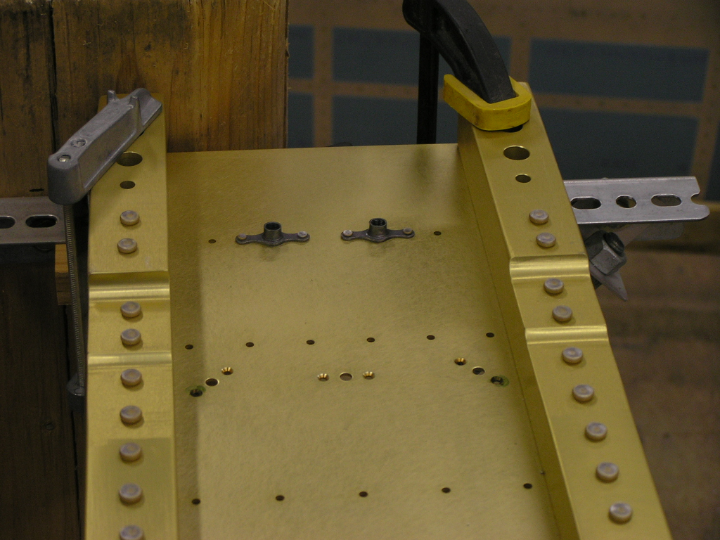
| 11/18/06 | Today my friend, Anton D'Allen came over to help
me out and proved to be a great helper. We started out by
match drilling the bottom skins.
After much debate I decided to go with Option 1. This
is the only option that avoids running the pitot tube and wiring
through the bellcrank area. I fabricated the attach angle
and drilled the bracket for riveting to the skin. I then
reattached the bottom skin and marked it for the pitot bracket
cutout. Cut the skin for the bracket and drilled for
rivets. I primed the pitot mounting tube and riveted the
platenuts. I will set the assembly aside until I rivet the
bottom skins. We clecoed the ribs in the leading edge assembly and mounted to the spar and clecoed. Fabricated the W-919 splice strip and drilled and clecoed with the W-908 rib. More Gretz Pitot install here. |
6.0 |
| 11/19/06 | Match drilled left wing leading edge. | 2.0 |
|
Total Hours |
35.0 | |
| Left Tank | ||
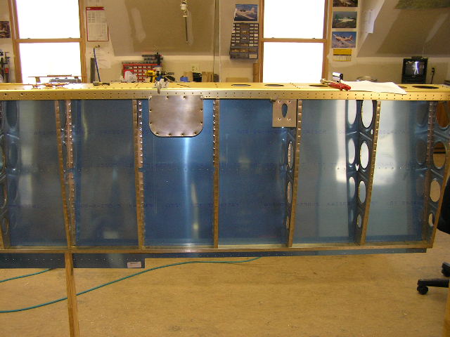
| 11/18/06 | I put the left tank skin in the cradle and clecoed the ribs.
I had to use my board and clamping technique in order to get the
clecos in but it worked. Next, I trimmed the T-911 and
T-911-INBD stiffeners, deburred and match drilled them to the
tank skin. Next, I carefully oriented the attach angles on the rear
baffle. Then, using the W-932DG drill guide, I drilled
each attach angle to #30. |
2.0 |
| 11/19/06 | Drilled attach angles to 3/16" for spar attach
and clecoed to tank baffle. Back-drilled attach brackets,
removed and deburred. Deburred tank baffle.
Re-attached baffle and clecoed to tank skin. Pop-riveted
the attach brackets to baffle. Installed tank to wing spar
and clecoed through spar with 3/16 clecos and through tank skin
to spar with 1/8 clecos. |
2.0 |
| 12/2/06 | Drilled the tank attach brackets through the
spar and then removed the tank from the spar. I had only
put one pop rivet in each bracket and as a result the brackets
moved as they were drilled. Sooo, off goes an order to
Vans for replacement brackets. I decided to go ahead and
order replacement elevator counterbalance weights since I seem
to have trimmed them to be too light. Started to
countersink the tank skin at the baffle attach. |
2.0 |
| 12/3/06 | Finished countersinking the baffle attach rivet
line. Drilled out the bad tank attach brackets.
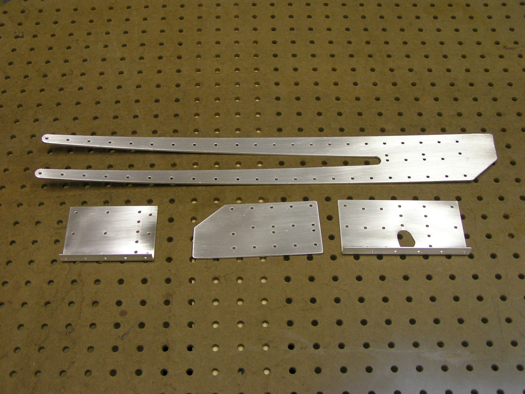
Trimmed the T-410 reinforcement plates. |
2.0 |
| 12/9/06 | I'm still waiting for the replacement tank
attach brackets so on to other tasks. I deburred the
bottom skin ribs and began deburring the bottom skins.
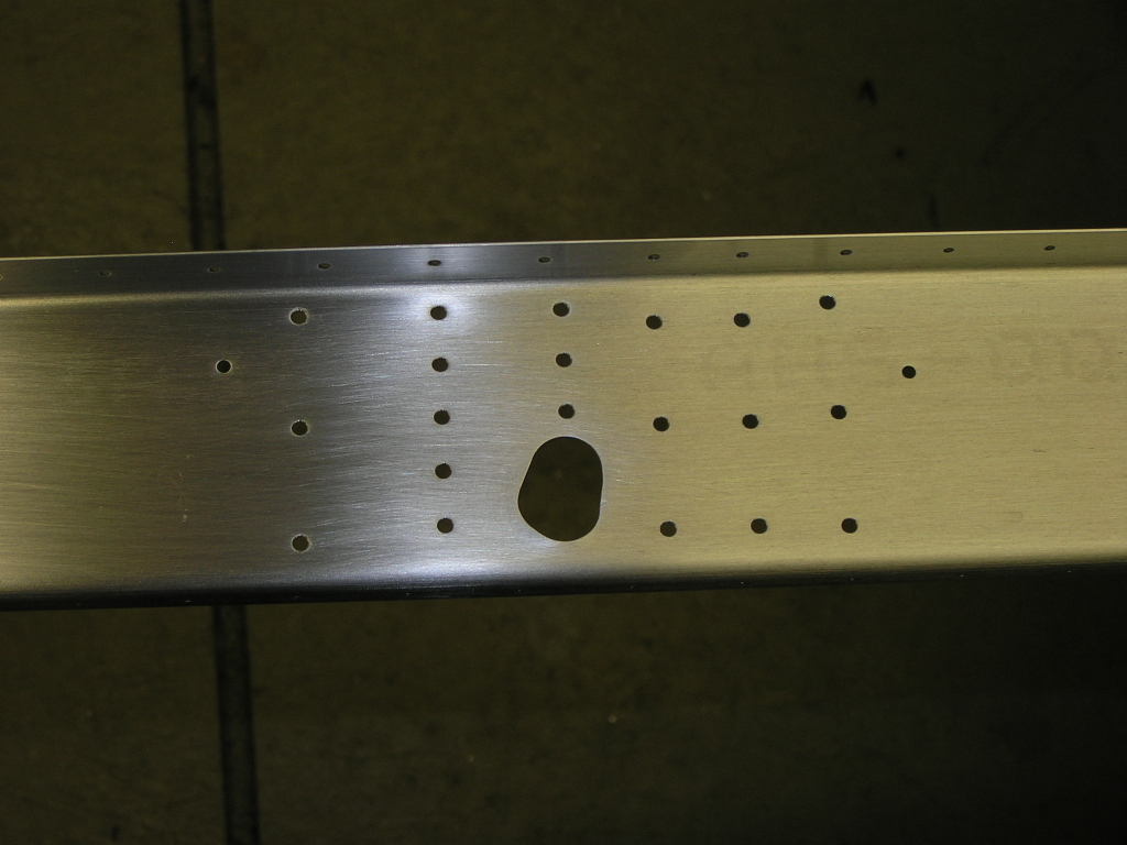
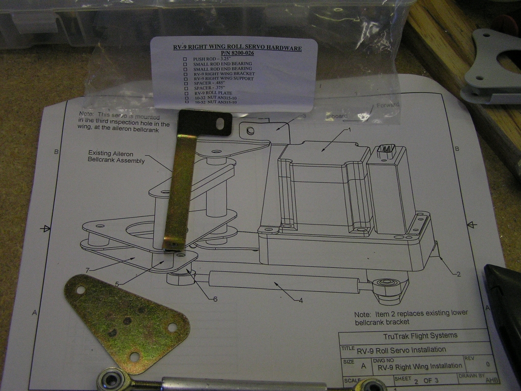
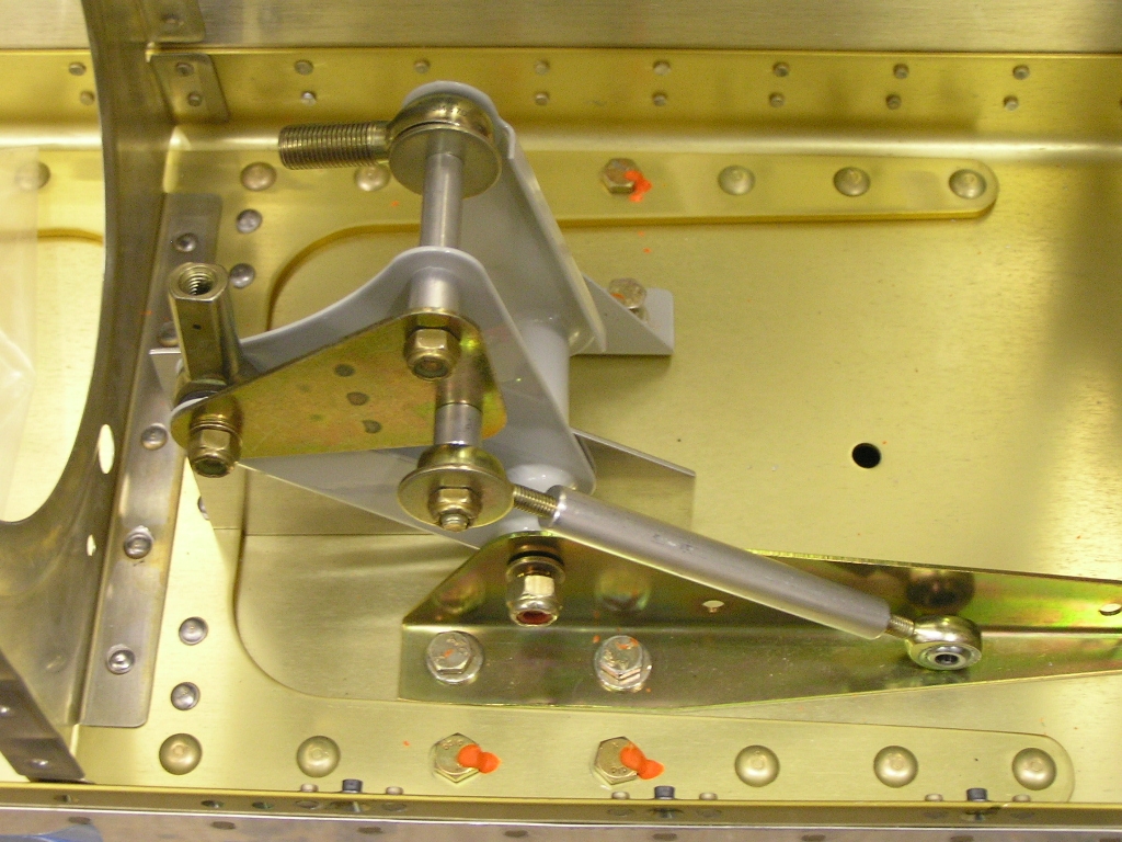
TruTrak Roll Servo Bracket Installation |
5.0 |
| 12/10/06 | Deburred the left wing bottom skins, then
dimpled. |
3.0 |
| 12/21/06 | Disassembled and deburred the leading edge skin,
ribs and splice plate. Drilled the splice plate for rivets
and deburred. Dimpled the splice plate. Used a
reamer to enlarge the hole for the tie-down bolt to final size.
Set aside for priming. My replacement tank attach brackets finally arrived today so I'm back in business. I drilled the brackets and pop riveted to the tank (using two (2) rivets this time). After back drilling through the spar, I removed the tank from the spar and placed in the cradle. I removed the attach brackets from the baffle by drilling out the pop rivets. Drilled the attach brackets for K1000-3 platenuts. Countersunk the brackets and washed down with MEK. Set the brackets aside for priming. Fabricated the T-905 attach angle. I used the bench
grinder to finish trim the angle.
I match drilled the attach angle to the inboard rib and set
aside for priming. |
7.0 |
| 12/22/06 | Primed the tank attach brackets. Riveted
the platenuts to the attach brackets. Fabricated the T-410 reinforcement plates to the inboard and outboard ribs and test fit/ground down until the fit was perfect. Deburred and match drilled the T-410 reinforcement plates to the inboard and outboard ribs. I match drilled the capacitive sender plates to the second and sixth ribs per the plans. Drilled the 3/8" hole for the BNC connector in the inboard rib. Deburred, dimpled and riveted the platenuts in the capacitive plates. Used the fly cutter to cut the access hole in the inboard #1 rib. Match drilled the T-411 plate. Drilled the 3/8" holes in the inboard rib for the fuel vent fitting and the fuel vapor return fitting. Fit and drilled the T-406B fuel cap flange. Deburred and
countersunk the flange. I also fabricated the T-914 clip from a
scrap of .020. |
7.0 |
| 12/23/06 | Countersunk the T-407 stiffener ring for the
platenuts. Deburred and countersunk the T-407 and riveted the
platenuts. Drilled the hole for the fuel pick-up since the
T-411 plate did not have it pre-drilled. Fit and match drilled the VA-112 drain flange. Drilled the holes in ribs #2 and #3 for the fuel return line and deburred. Chemically treated leading edge ribs, splice plate, T-905 attach angle and T-411 cover plate. Disassembled tank and deburred stiffeners and ribs.
Deburred skin. Fabricated the small plate for covering the
tooling hole in the outboard rib. Drilled and deburred cover
plate. Scuffed skin along rib and stiffener line. |
6.0 |
| 12/26/06 | Dimpled leading edge and left tank skins.
Set up area and prosealed and riveted stiffeners, fuel flange, drain flange
and cover plate for tooling hole in outboard rib. I used
my new (used) pneumatic Semco dispensing gun for dispensing the
proseal and it worked great. Riveted the platenuts on the
splice plate. |
6.0 |
| 12/27/06 | Prosealed and riveted tank ribs #2-#6.
Drilled anti-rotation bracket to T-411 tank access cover plate. |
5.0 |
| 12/30/06 | Prosealed and riveted the inboard and outboard
ribs. Riveted the T-905 attach angle and the T-410
reinforcement plates.
Prosealed and riveted the anti-rotation bracket to T-411 tank
access cover plate. |
3.0 |
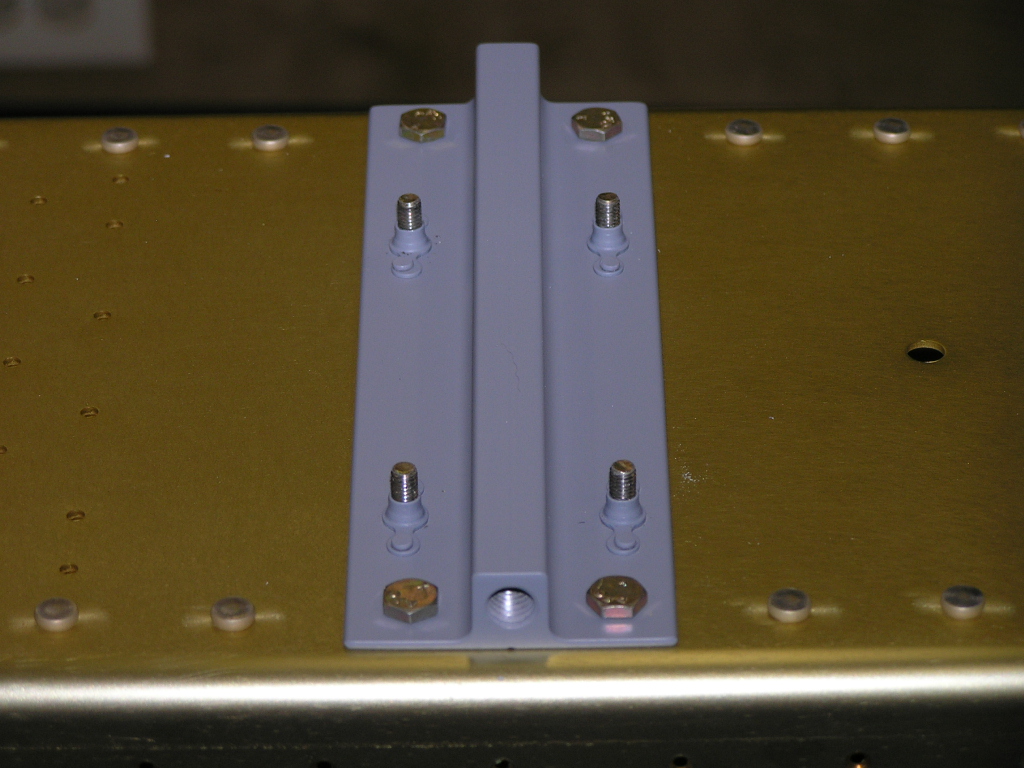
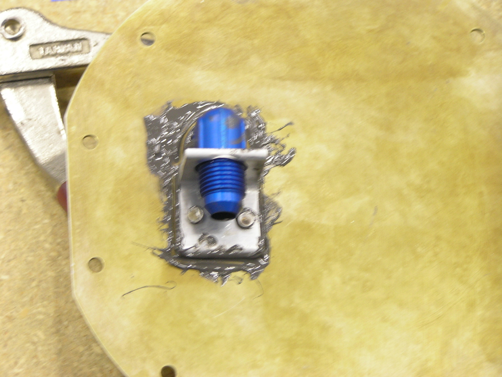
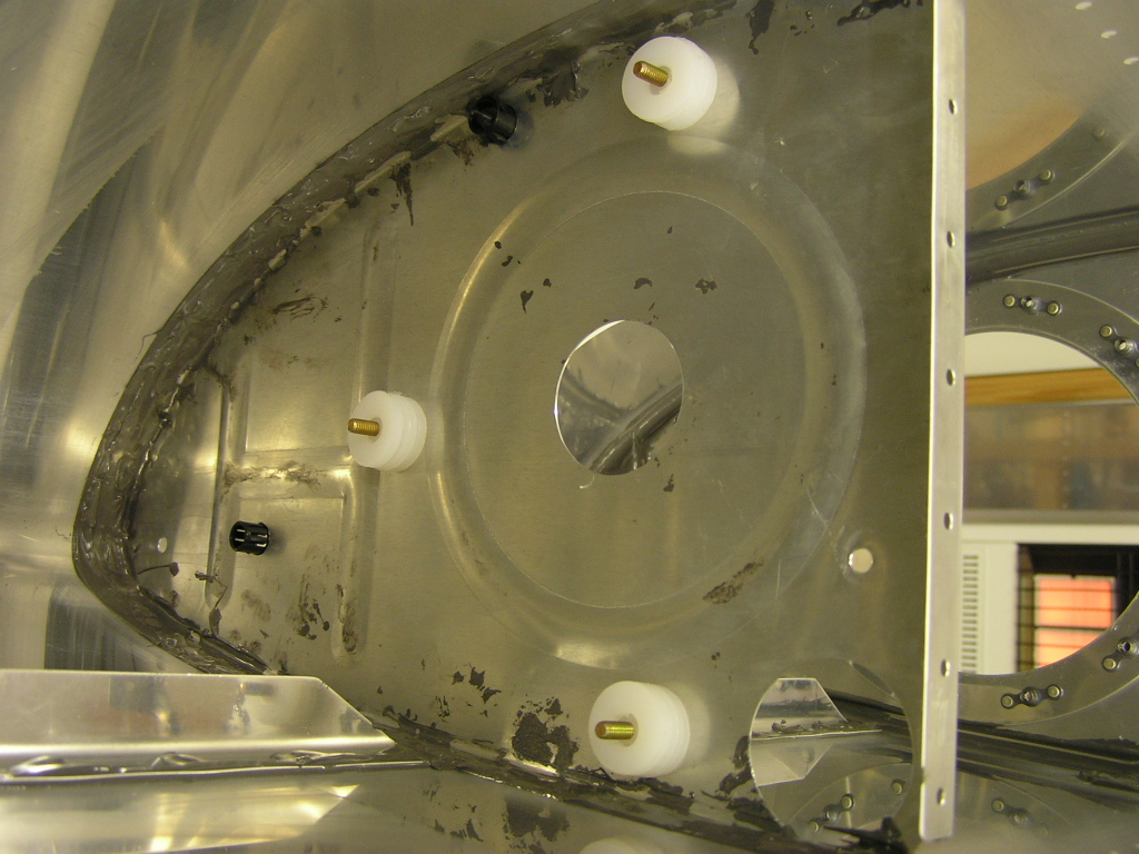
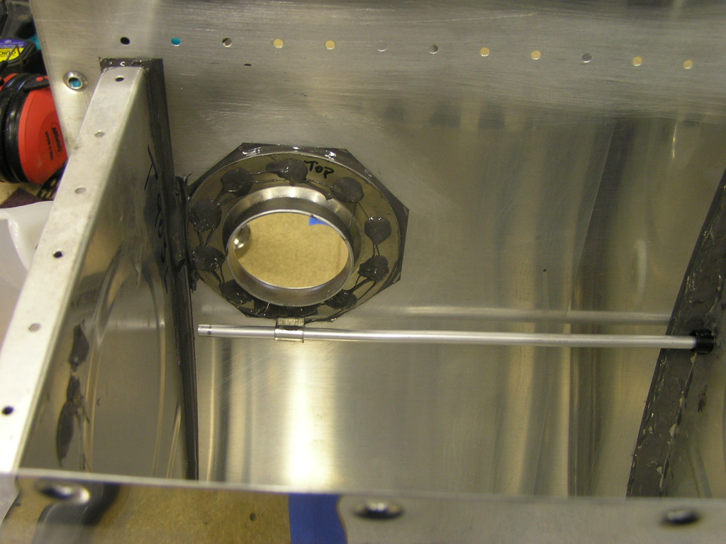
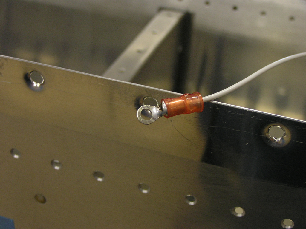
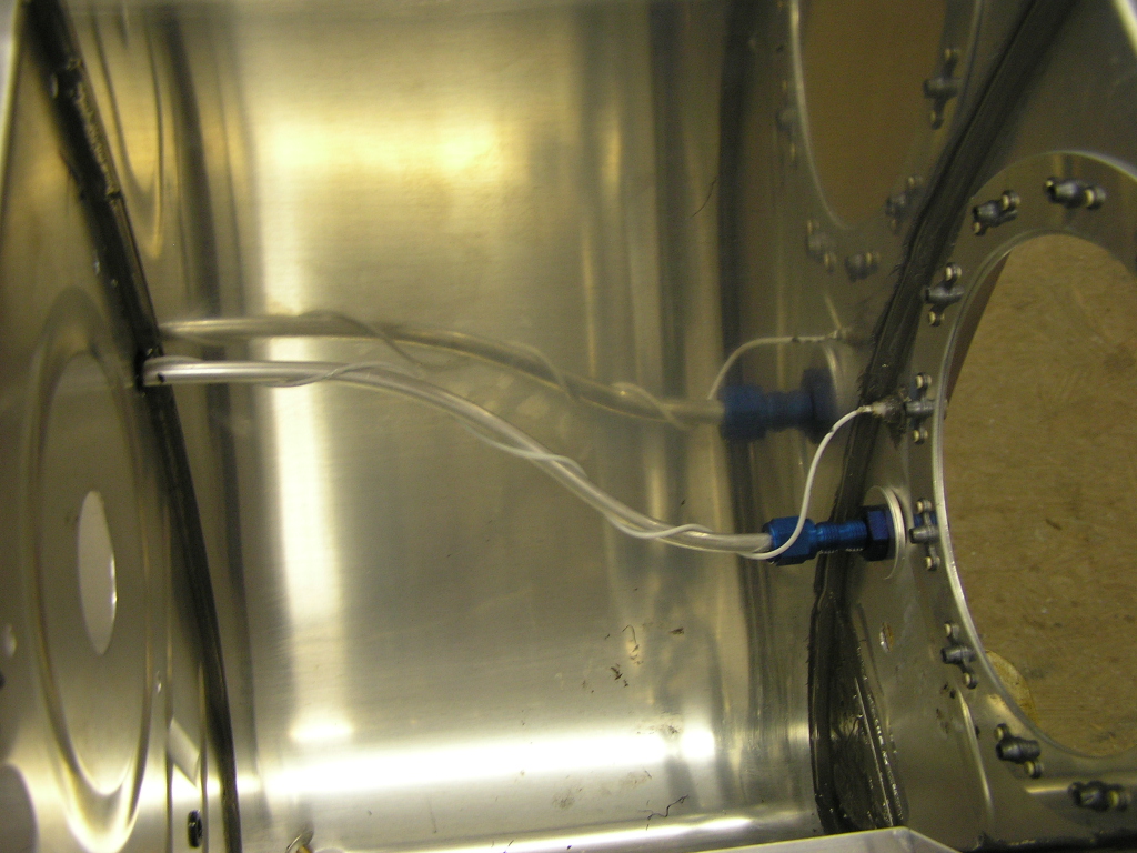
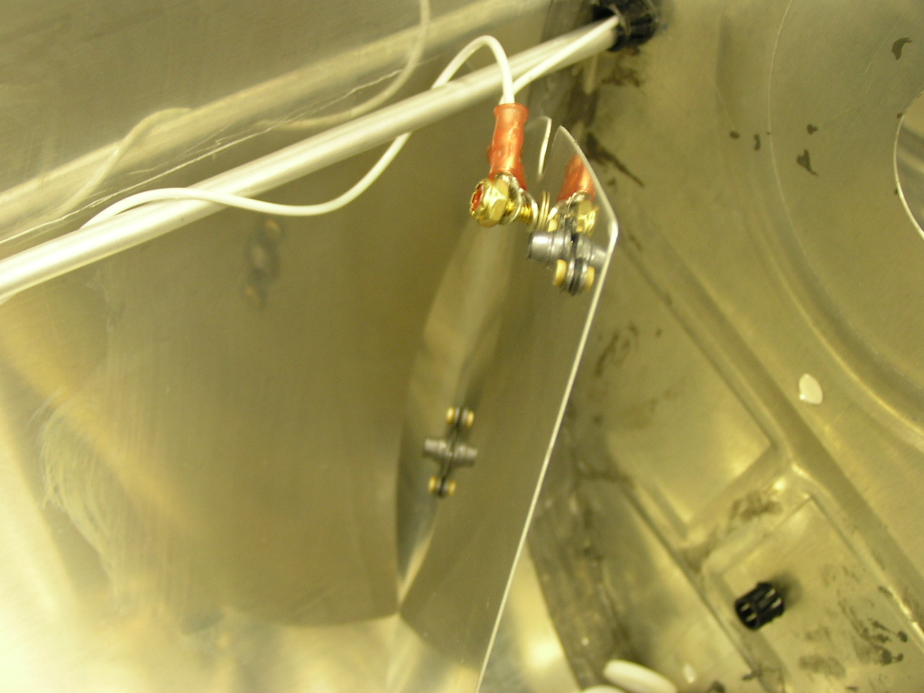
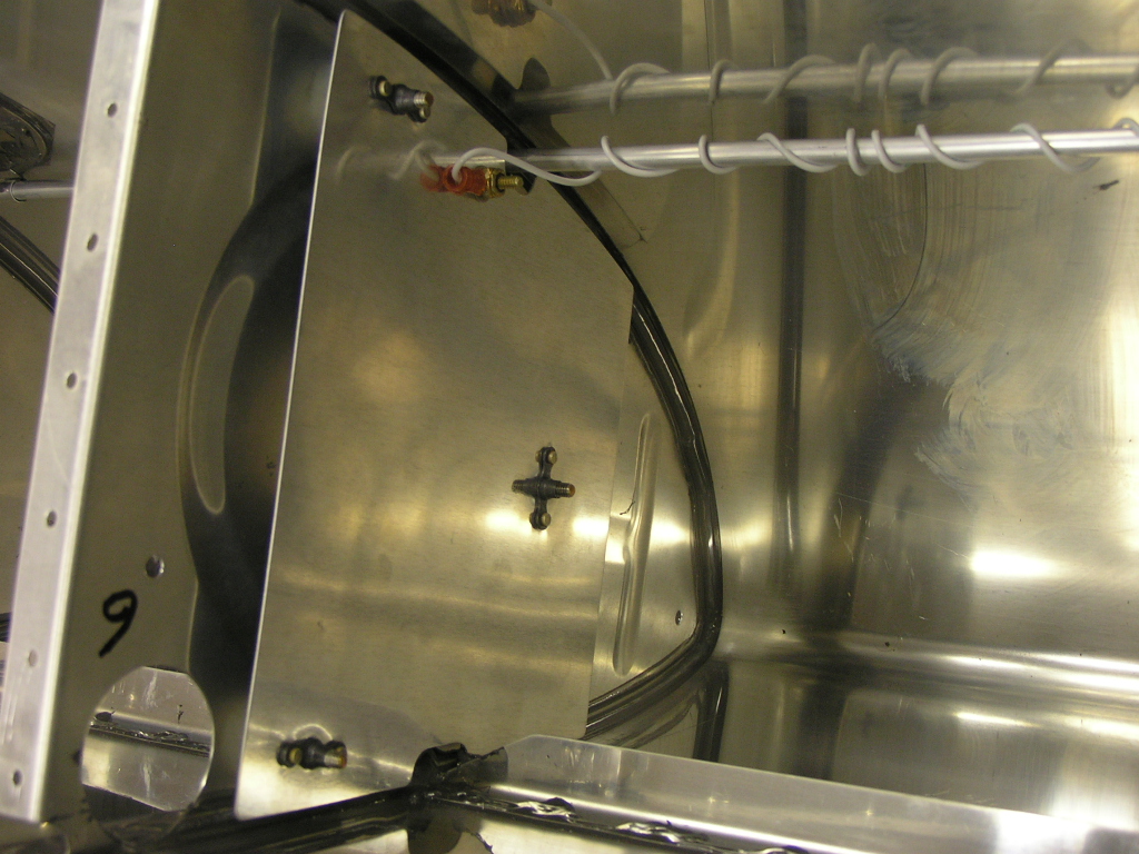
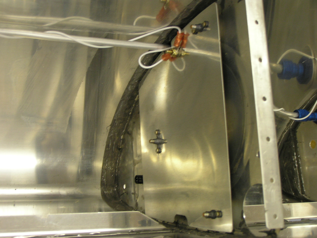
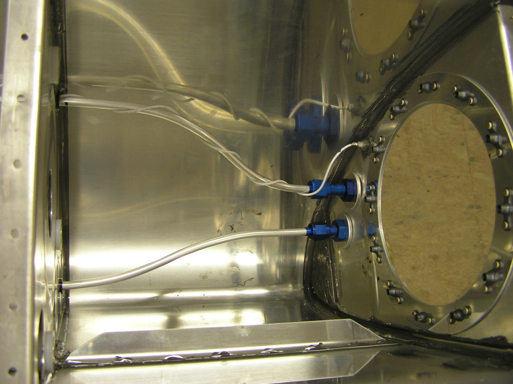
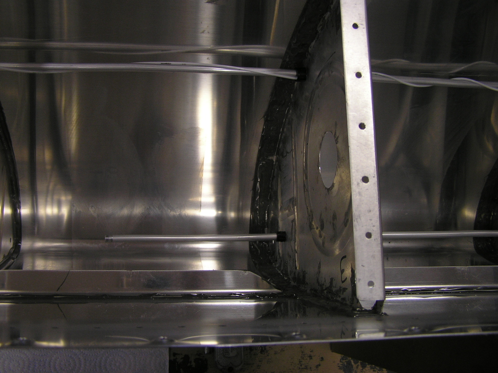
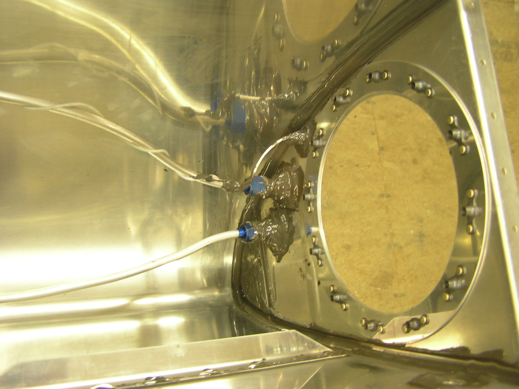
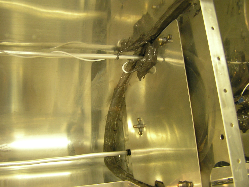
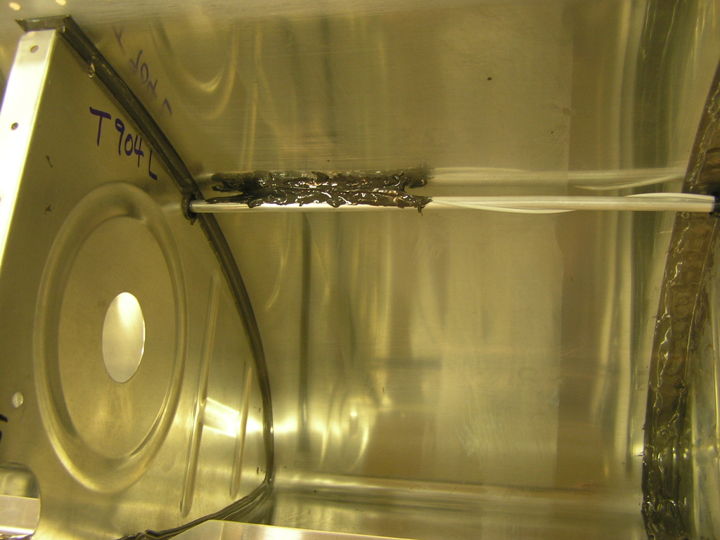
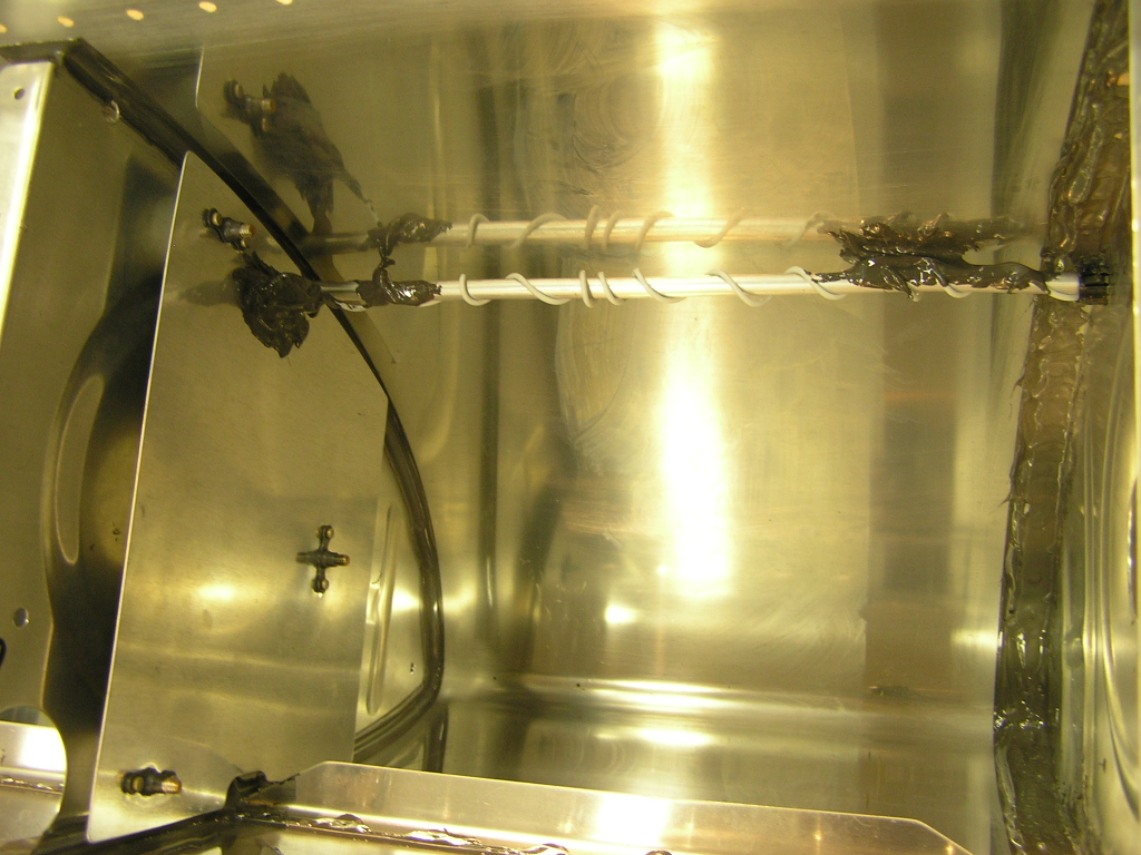
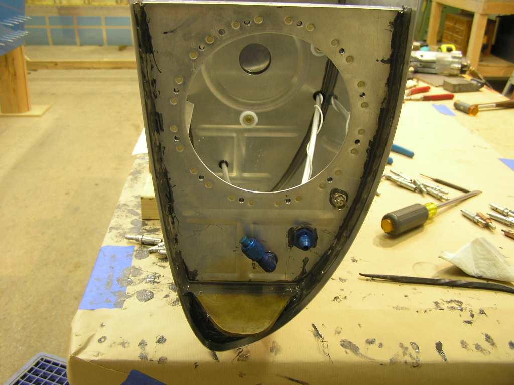
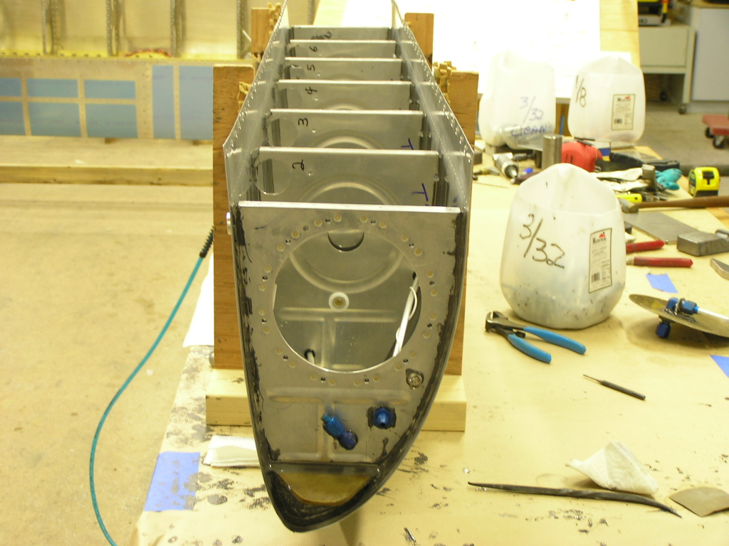
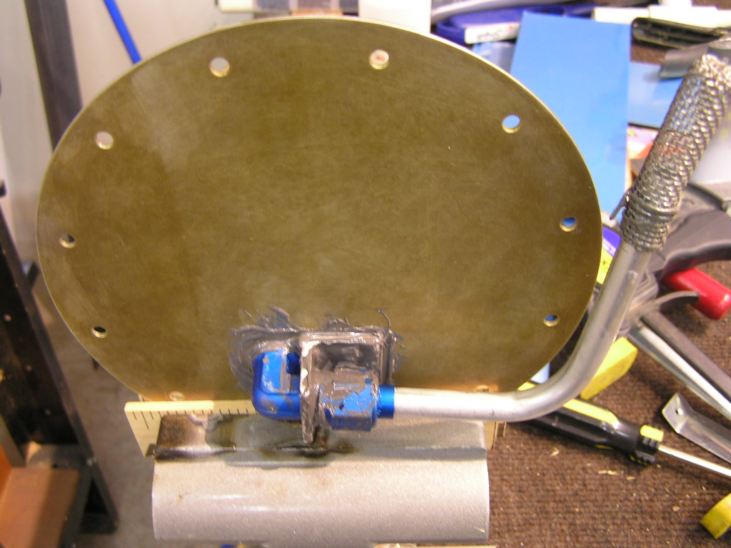
| 12/31/06 |
Capacitive
Sender Installation I wanted to detail the installation of the capacitive senders for the fellow builders who would like to see the details. I
started by loosely installing the inboard and outboard
capacitive plates. Then installed the BNC sender in the
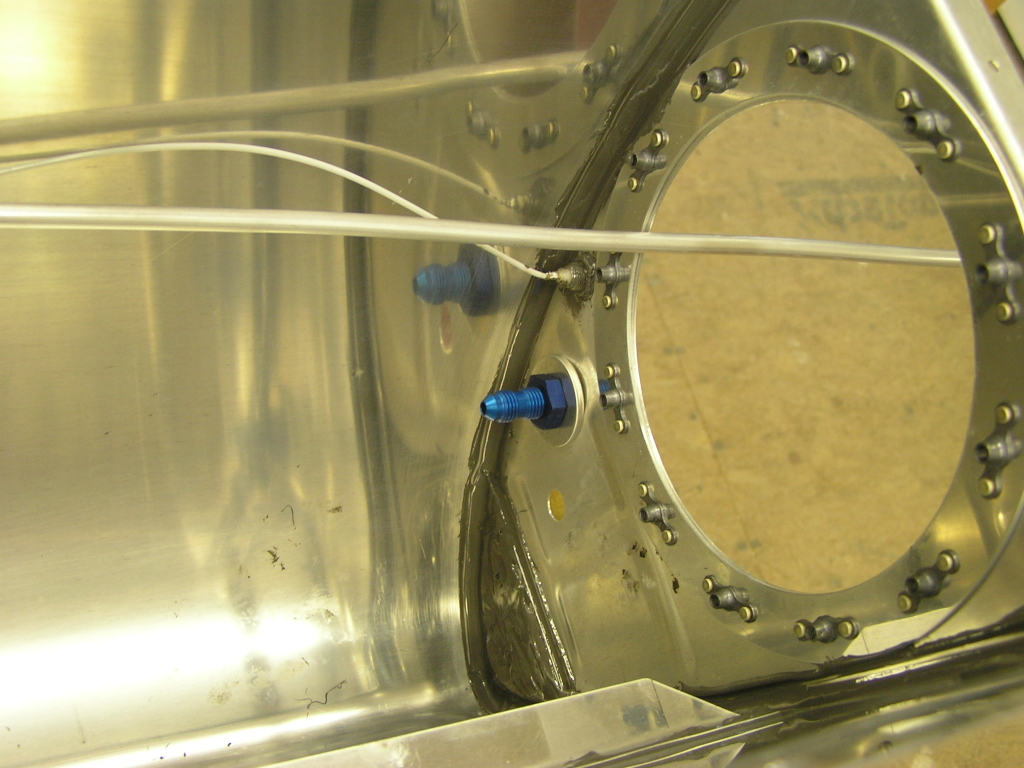
inboard rib. I rough installed the vent tube and when I had the proper
length I flared the end and loosely installed to the AN-4
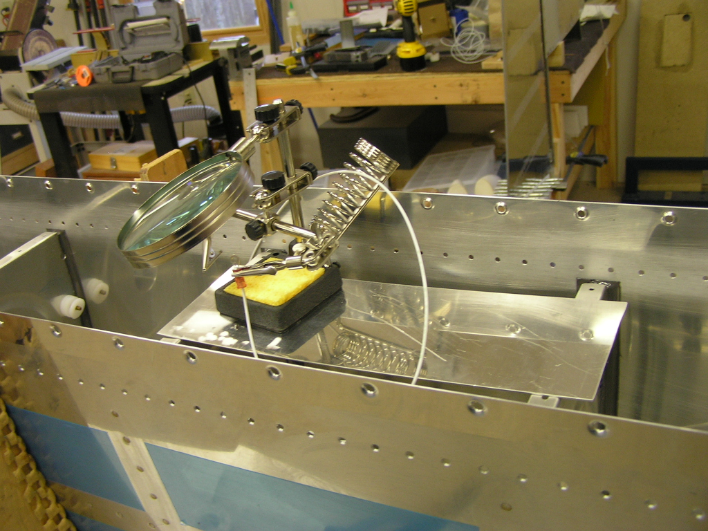
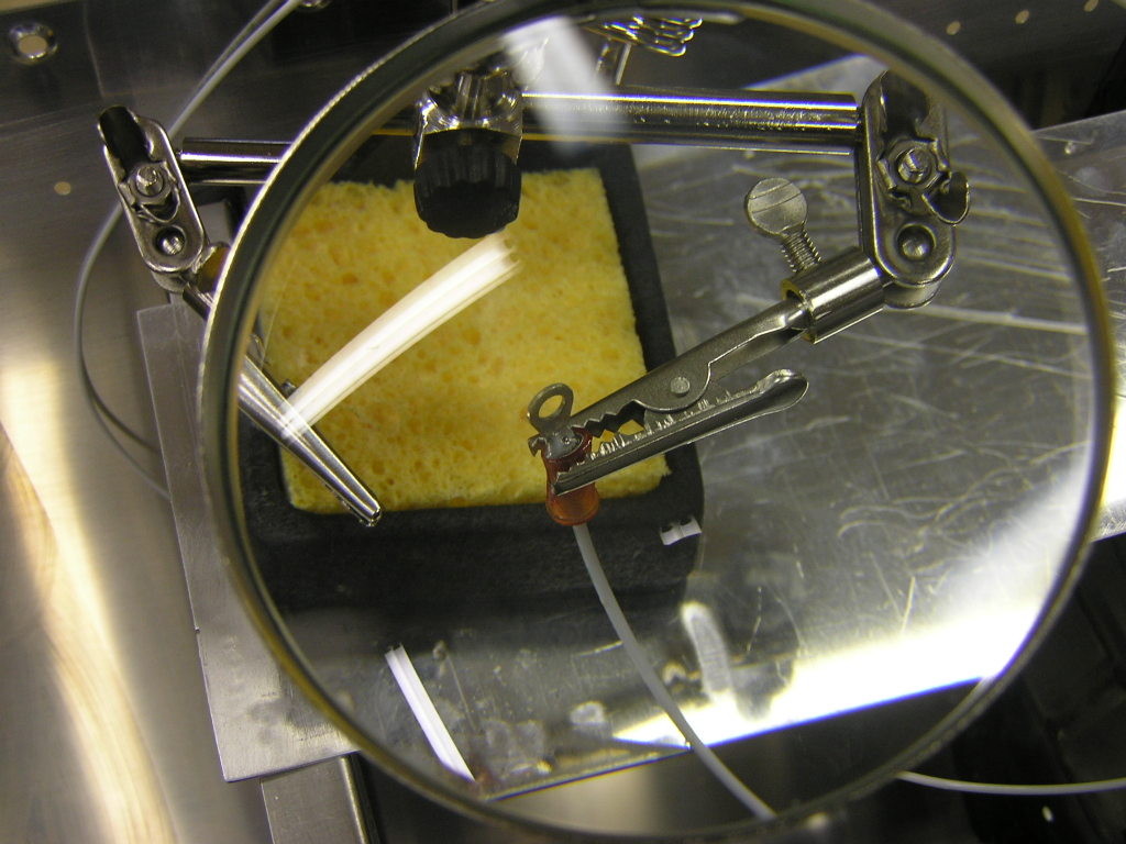
bulkhead fitting. Next, I crimped and then soldered the ring connectors on the
wire ends. I then twisted the 18 AWG wire around the vent tube to secure
the wire and remove the excess slack. Then I loosely
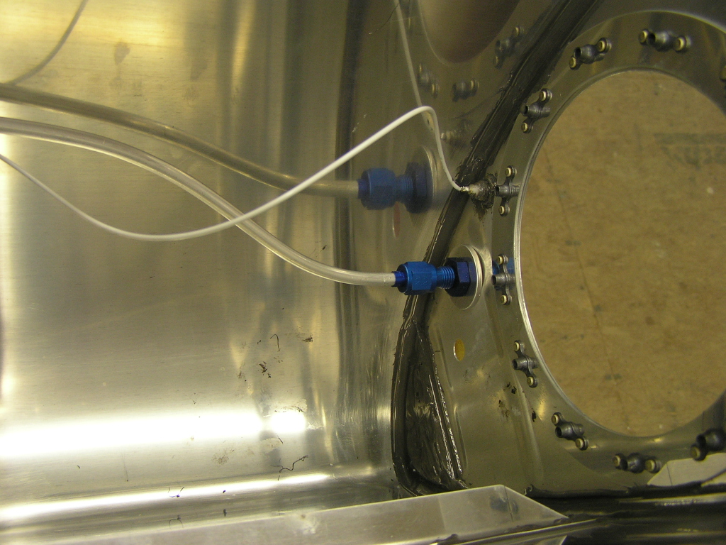
connected the connectors to the capacitive plates. Then I installed the plates permanently. Next, I installed the fuel vapor return line. Like the
right wing tank, I ran the return to the middle of the third
bay. Finally, I mixed up 4 oz. of proseal and coated the bulkhead
fittings of the vent tube and vapor return line and torqued to
55 in/lbs. Then I covered the entire fittings with
proseal. I also covered the ring connectors and connector
screws and nuts. I also prosealed the wire in places where
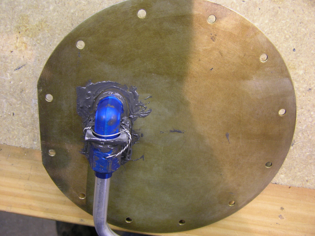
it could rub against the tank skin. Here is the final shots before I close up. Installed the fuel sender with proseal and safety wired. |
7.0 |
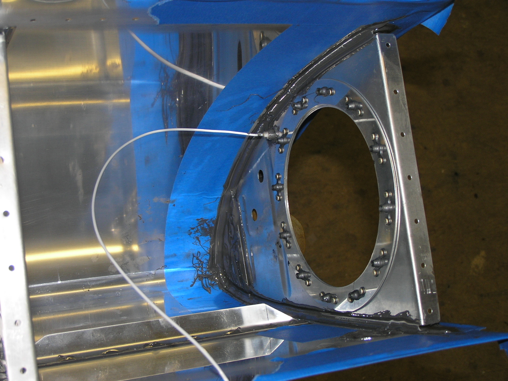
| 1/1/07 | Prosealed along rivet lines and attached baffle
with clecos in every hole. Attached and prosealed tank
attach brackets. Riveted baffle to tank, riveted baffle to
rib flanges and riveted tank attach brackets to baffle/rib
flanges. |
4.0 |
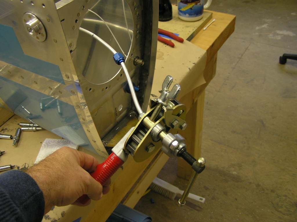
| 1/5/07 | Mixed 2.0 oz of proseal and applied to the
inboard rib around the cover plate. Applied the cover
plate and, after swirling each screw in proseal, attached
permanently. Now to let the proseal cure for about a week
and test for leaks.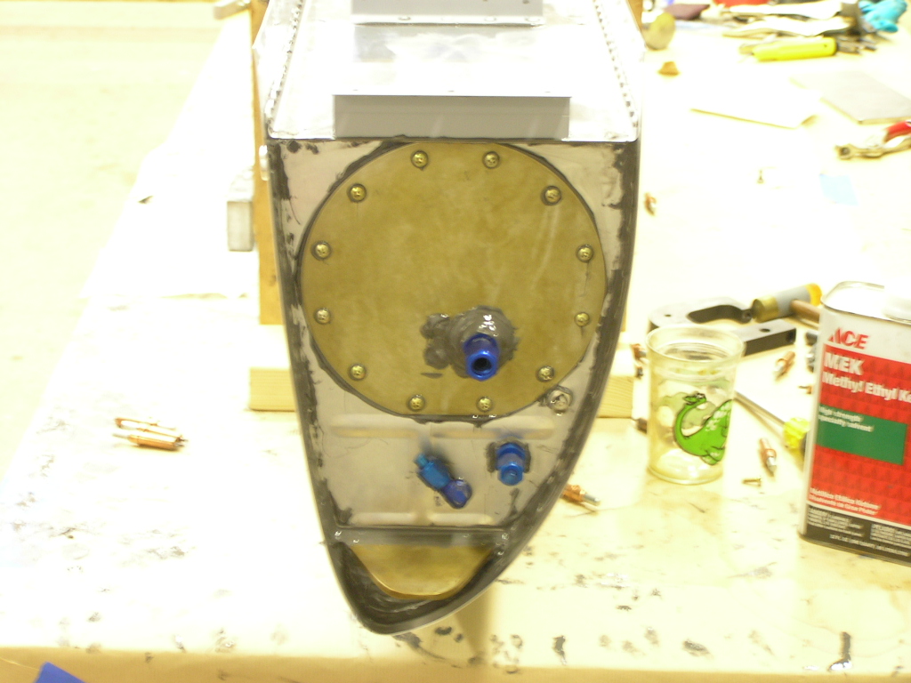 LEFT
TANK DONE! |
.5 |
| 1/13/07 | Tested tank for leaks. NO LEAKS! |
.5 |
|
Total Hours |
62.0 | |
| Closing Left Wing | ||
| 1/6/07 | Deburred top outboard wing skin and began
dimpling. |
2.0 |
| 1/7/07 | Dimpled top outboard wing skin. Deburred
top inboard wing skin and the wing walk doubler and dimpled
both. Deburred J-stringers and dimpled. Began deburring
wing ribs and rear spar in preparation for dimpling. |
7.0 |
| 1/11/07 | Received notification from Van's
yesterday that my fuselage kit will be shipped the week of February
5th. I had better get moving to finish the wings. I
finished deburring the main wing ribs and rear spar and started
dimpling. |
1.0 |
| 1/12/07 | Finished dimpling main wing ribs and rear spar.
Used deburring tool to "ream" the dimples in the rear spar.
Now it's time to prime! |
2.0 |
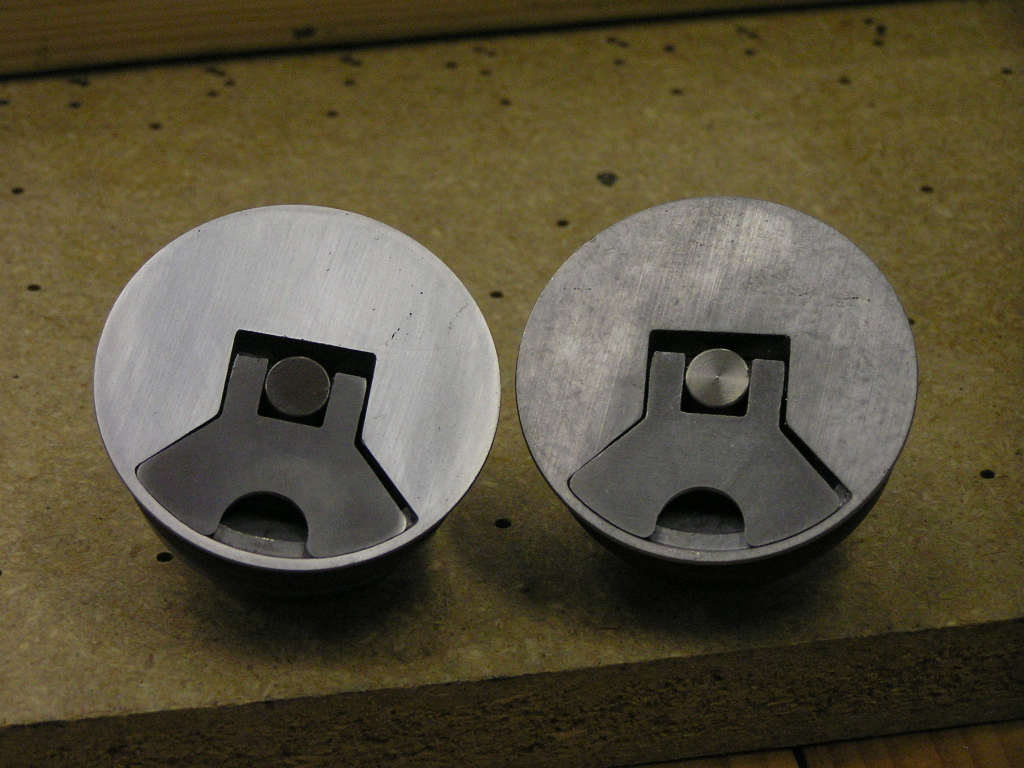
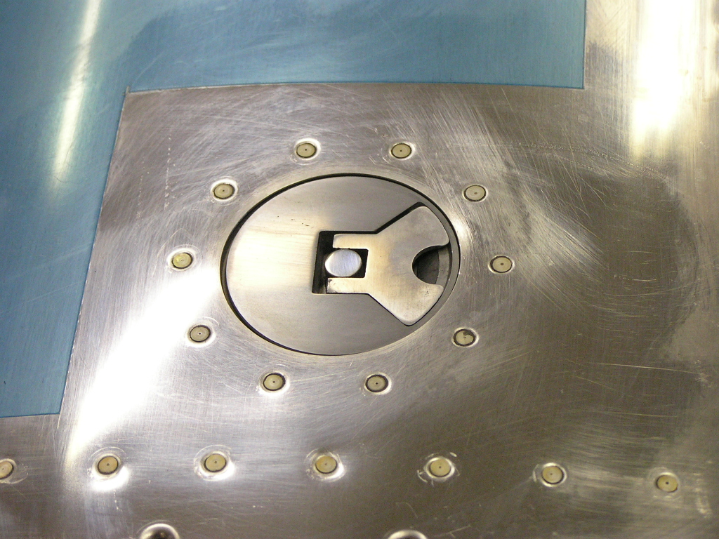
| 1/13/07 | Chemically treated the leading edge skin.
Polished one of my fuel tank caps. Several builders are
opting to buy the Van's "deluxe" fuel caps. I couldn't
justify spending an additional $100 per cap so I made my
own. I started by disassembling the cap. Next I
started sanding with 240 grit sandpaper. I progressed
through 320 grit, 400 grit, 600 grit and finally wet sanded with
1000 grit. All in all it took 30 minutes for the first
cap. |
3.0 |
| 1/14/07 | Began riveting the leading edge together. |
1.0 |
| 1/19/07 | I finished riveting the leading edge and placed
on the spar. I started riveting the leading edge to the
spar and riveted all that I could reach by myself. I began the
process of chemical treating the inside of the top skins as well
as the wing walk doubler and the J-stringers. Since it was
around 26º
outside and the water froze on contact with the skins, I was
only able to clean scuff the skins and chemically clean/etch the
skins. |
3.0 |
| 1/20/07 | Today my friend and fellow EAAer, Jim Olsen,
came over to help me rivet the top skins. I started by
chemically treating the inside of the skins and set them aside
to dry. Jim helped me by bucking the inside spar flanges
of the leading edge. We then used the pneumatic squeezer
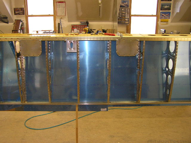
to rivet the top and bottom to the spar flange. Next we mounted the fuel tank and bolted it to the spar. The bolts were torqued to 25 in/lbs. Next we screwed the tank top and bottom to the spar flange. I was pleased to see there was no gap between the leading edge and the tank. We then clecoed the inboard and outboard skins to the spars and ribs. My EAA Technical Counselor, Kyle Boatright, called as he was heading our way for a visit so we met him at Copperhill airport. Kyle had not seen the project since I had received the wing kit so he looked it over pretty well. I really like having Kyle looking over my shoulder not only because he has built an RV but because he is exceptionally knowledgeable in so many areas of aircraft construction. With Kyle's letter of approval, we returned him to the airport. After a great Mexican food lunch, Jim and I returned home and
riveted the top skins. Like the right wing, we
back-riveted the top skins and then riveted the J-stringers.
We then removed the wing from the stand and placed it in the
cradle. After Jim left, I finished riveting the skins to
the rear spar. |
8.0 |
|
Total Hours |
307.2 | |
| Next: Wings 3 |