
Home
Shop
Tools
Empennage
Wings
Right Wing
Right Tank
Closing Right Wing
Wings 2
Wings 3
Wings 4
Fuselage
Panel
Firewall Forward
Canopy
Wiring
Miscellaneous
Wings
|
Date |
Description of Task | Hours |
| Right Wing | ||
| 5/5/06 | Faxed order to Van's. | .2 |
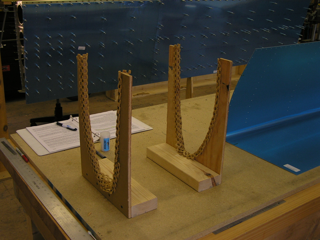
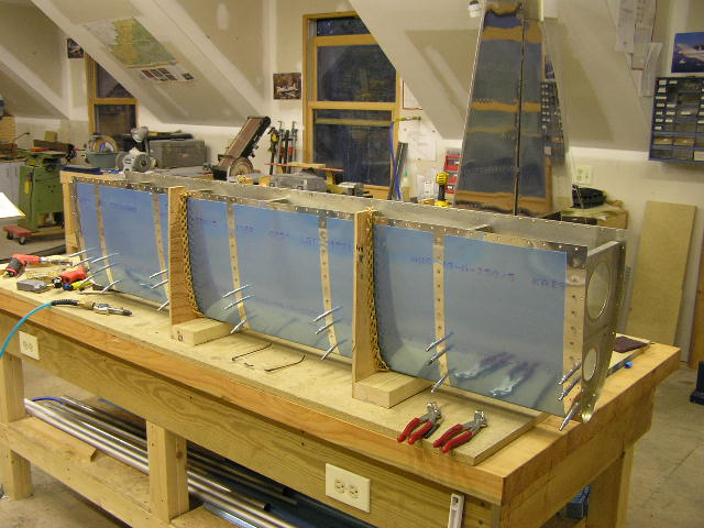
| 5/21/06 | Set up the wing stand. When you live in a
log home, you gotta keep the design constant. (It also helps to
have leftover logs).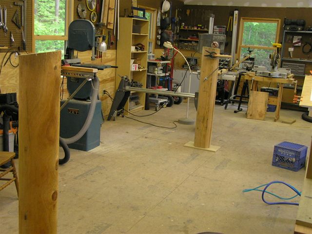 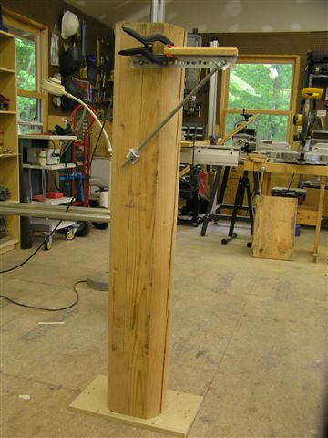 |
2.0 |
| 5/31/06 | Finally arranged a visit from my EAA Tech
Counselor, Kyle. He inspected my construction technique
for the empennage and deemed it is "acceptable". While he
admitted the work was awesome, he noted that the FAA prefers
more sterile language...so "acceptable" it is! I also got
notification from Vans that my slow-build wings will ship on or
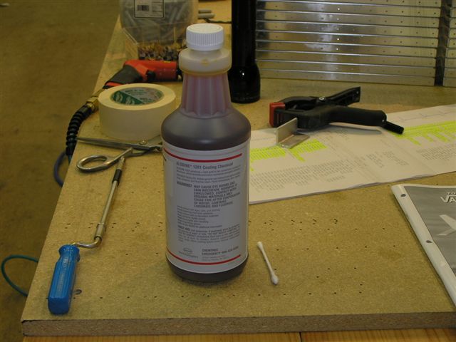
before July 10th! Today I also ordered a quart of alodine
from ACS as well as another gallon of Sanchem. |
1.0 |
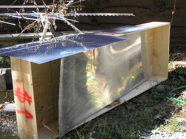
| 7/20/06 |
WINGS ARRIVE!! Offloaded the crates from the FedEx
Freight truck to my Dodge Dakota truck at the entrance to my
driveway because the driver would never be able to turn around
the tractor and 40" trailer if he drove in to the shop.
BTW, freight from Vans to Mineral Bluff, GA was $399.10... I decided to unpack the crates on the truck since I was alone and started inventorying. |
2.0 |
| 7/21/06 | Finished the inventory. I only had one,
two-inch piece of 1"x1" aluminum angle missing from the
kit...Guess I'll call Vans's on Monday. I got everything
organized and had a lot of trash to haul out.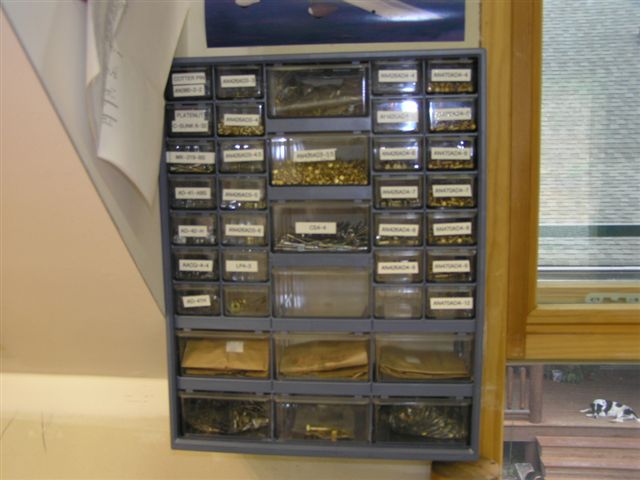 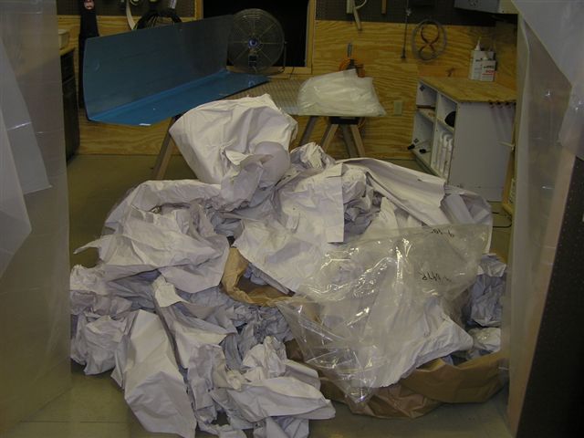 |
2.0 |
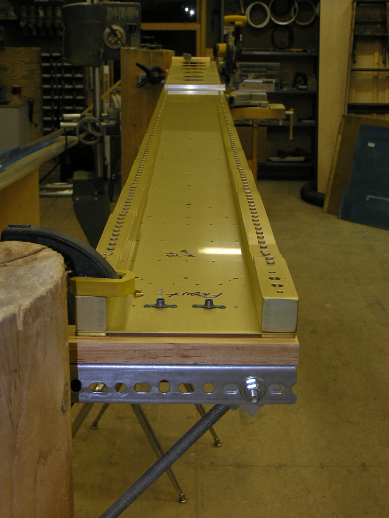
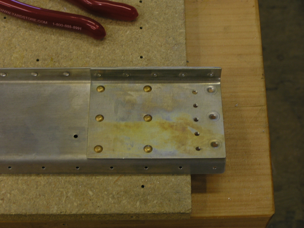
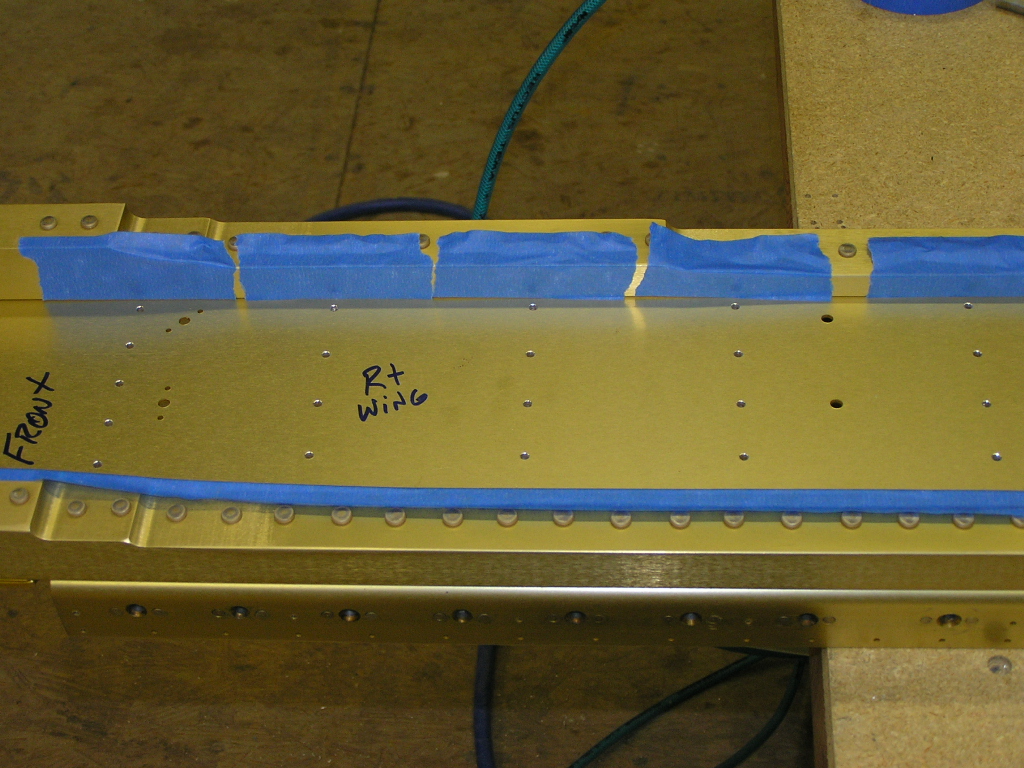
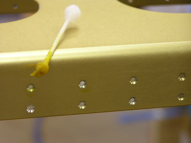
| 7/22/06 | Today I started by setting up the right wing on
the stand and clamped it down. I plan to build the right
wing first, and then the left.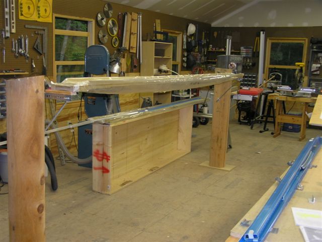 I drilled the spar to #40 for the 124 platenut rivets. Then I countersunk the rivets and deburred the back of each hole. I then dabbed the countersinks with Alodine using a Q-tip. I began riveting the #8 platenuts. I also tested countersinking the platenut for the #8 screw. (Thanks to Mike Schipper and Smitty for their tip on going slow with the cutter in order to keep a nice countersink) I also cut off a #8 screw and used it to gauge the countersink depth. 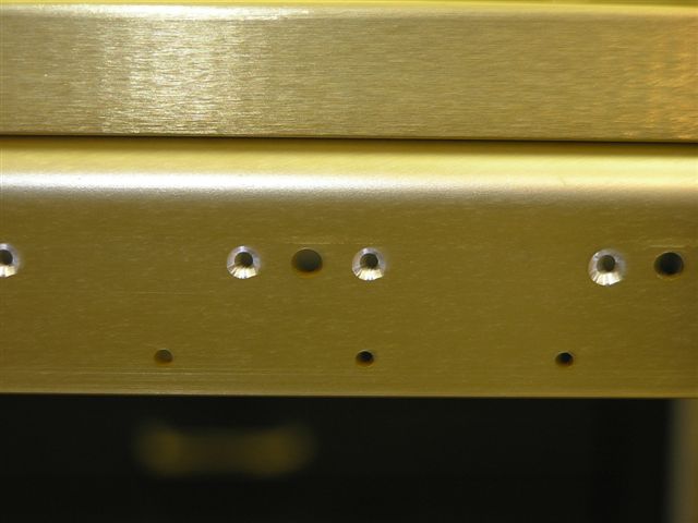 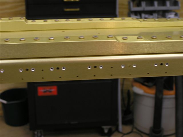  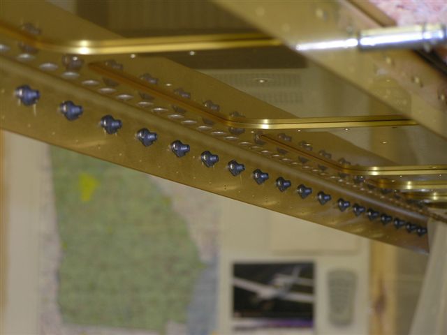 |
4.0 |
| 7/23/06 | Finished countersinking the spar for the #8
screws...all 62 of them. Alodined each countersink.
I edge deburred the access plates. I countersunk the spar
to install the #6 platenuts for the access plates.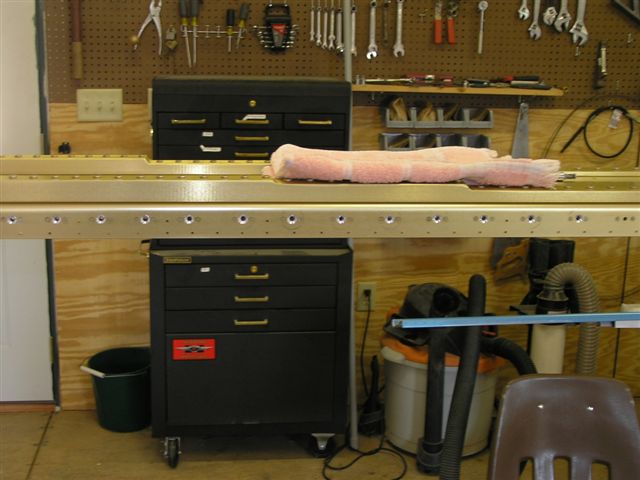 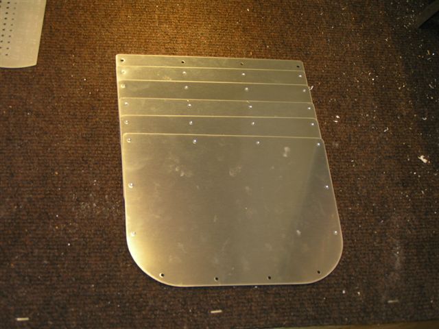 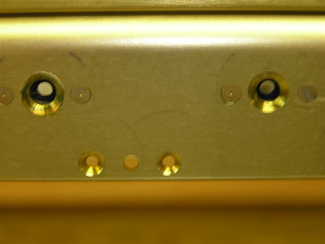 |
4.0 |
| 7/24/06 | Riveted the nutplates for the access plates and
countersunk the screws. |
.5 |
| 7/25/06 | Alodined the access plate screw holes.
Drilled, deburred and dimpled the #8 holes on all six access
plates.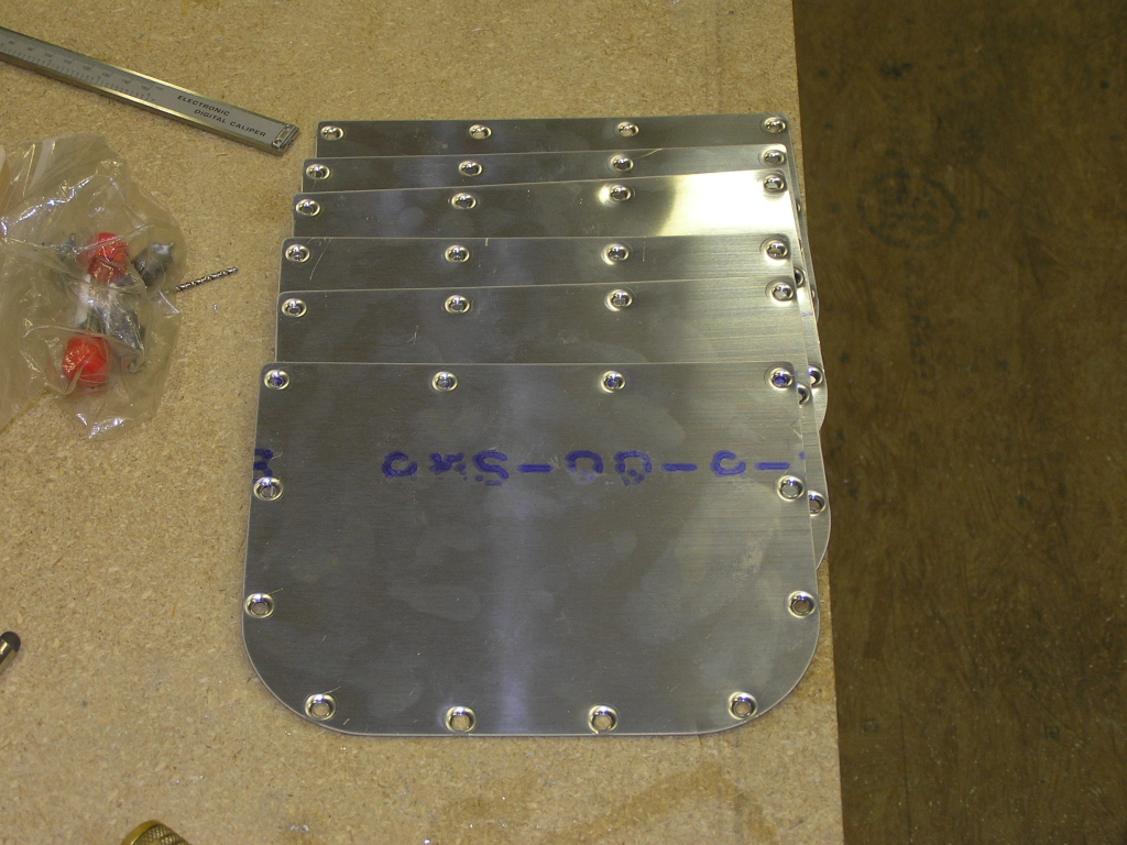 |
.5 |
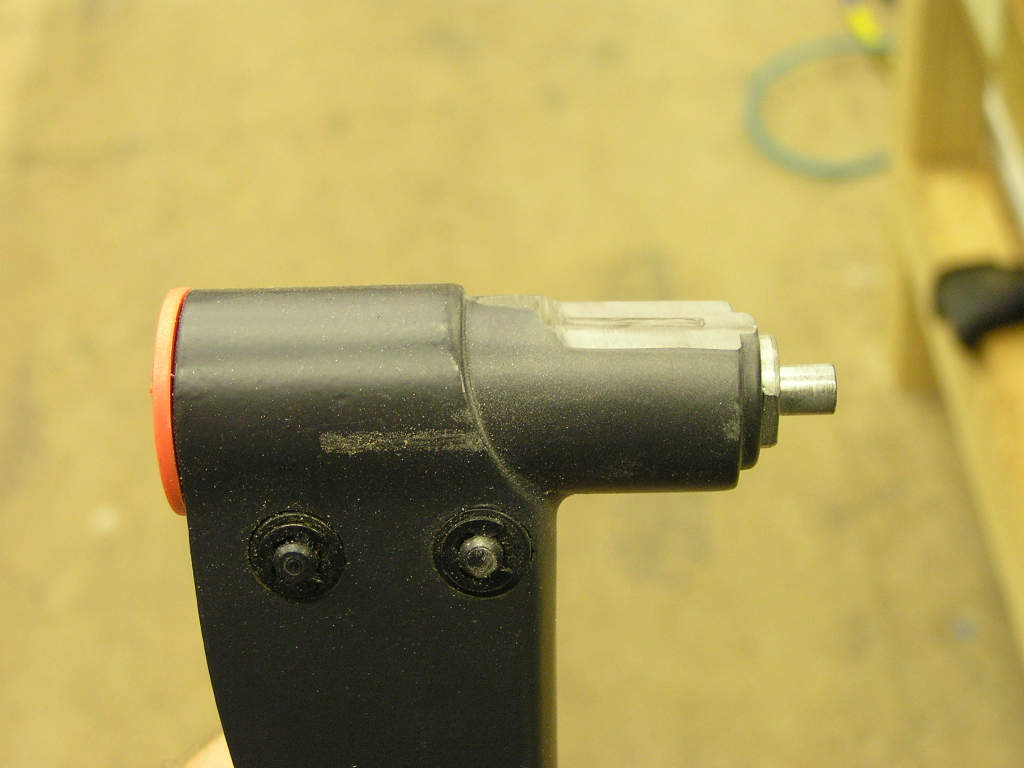
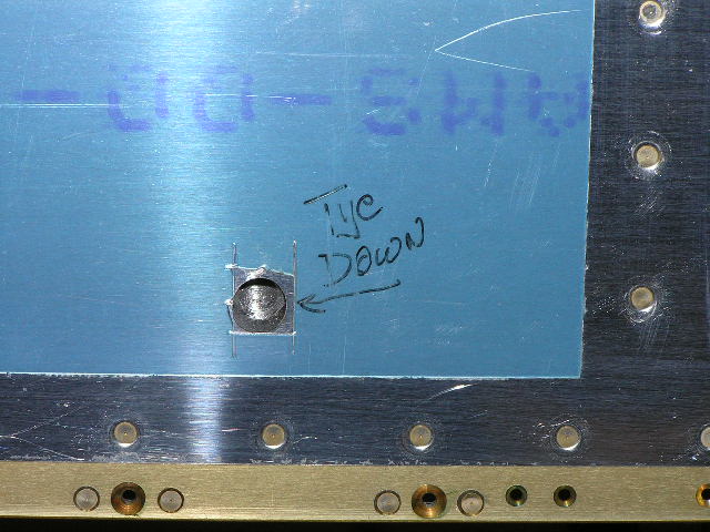
| 7/28/06 | Today I received my delrin rudder stop made by
Jeff Bordelon in Austin, TX.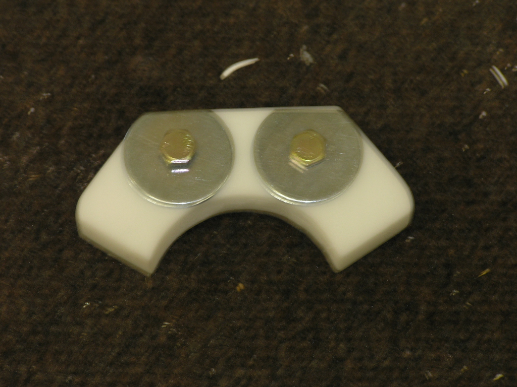
Drilled and riveted the two center section platenuts on the
spar. Cut the tie-down bars (both) to length and deburred.
I realized my tap was the wrong thread so I will need to pick up
the correct one before I can tap the ring hole. I went
ahead and drilled the four attach holes as well as the four
platenuts. Attached the four platenuts and primed using
the rattle can. |
3.0 |
| 7/29/06 | Began working on the Rt. wing rear spar.
Drilled and clecoed the W-907D and W-907E doubler plates to the
spar. Drilled the hole for the aileron pushrod using my
Unibit then cleaned it up with a sanding drum in my Dremel tool. Took
the whole assembly apart and deburred the spar and doubler
plates. 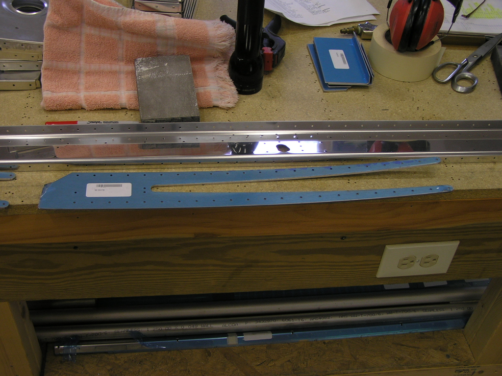 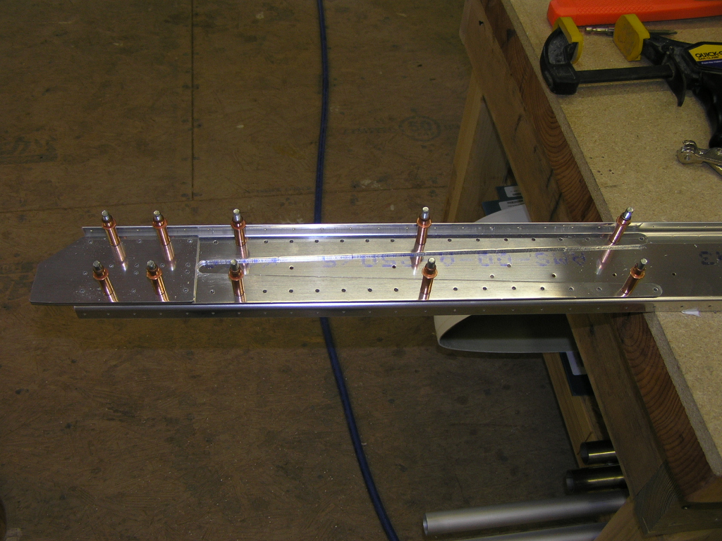 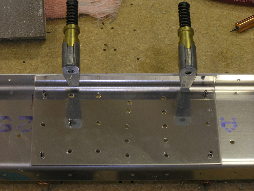 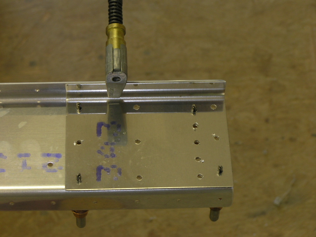 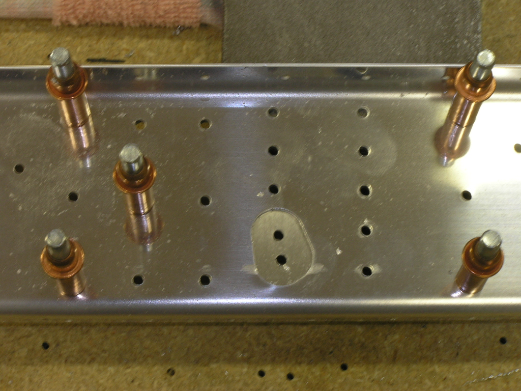 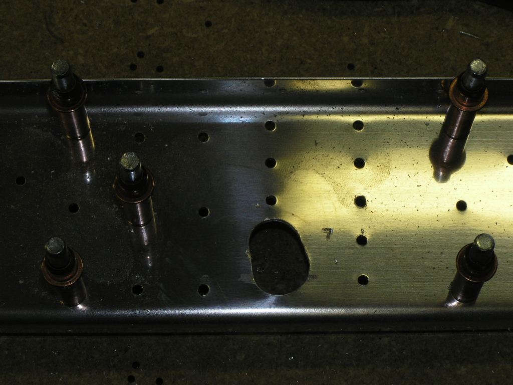
I will be using the SanChem chemical conversion on this plane
for all internal spars, ribs and skins. I am using SEM
self-etching primer in a rattle-can for small parts as well.
I have a full description on this product and how it compares
with alodine in the
Empennage
section of the website. I SanChemed the rear spar and
doubler plates. |
6.0 |
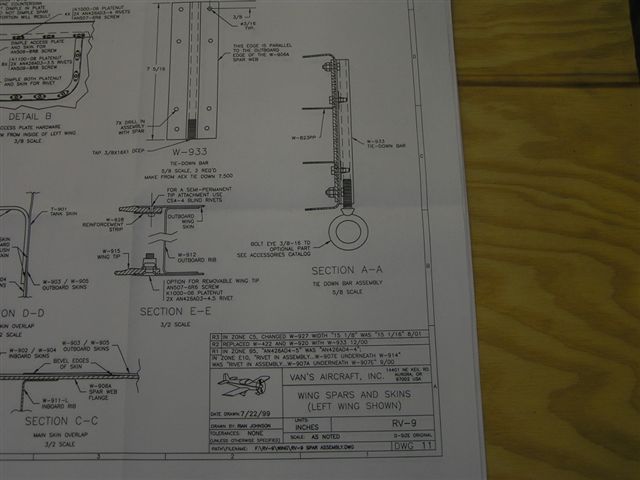
| 7/30/06 | Dimpled the top holes to accept the skins.
Riveted the doubler plates to the rear spar. A problem I
had was the Dwg 11 plan sheet was a "blotched" print. I
called Vans and they are sending me a clean copy.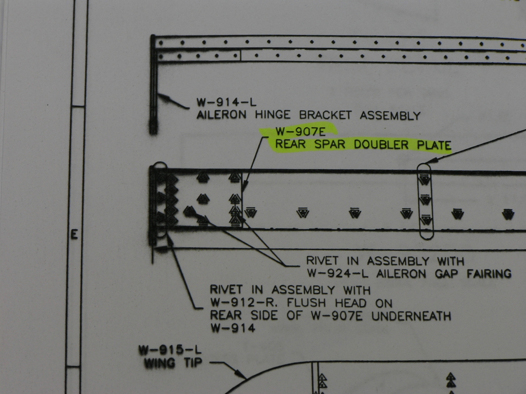  Saved myself some time and just referenced Smitty's website to determine which holes received rivets and which should not. Yeah, I know, that's really cheating....But go back and look at the plans again and YOU try to determine what size rivets (and where) they go. 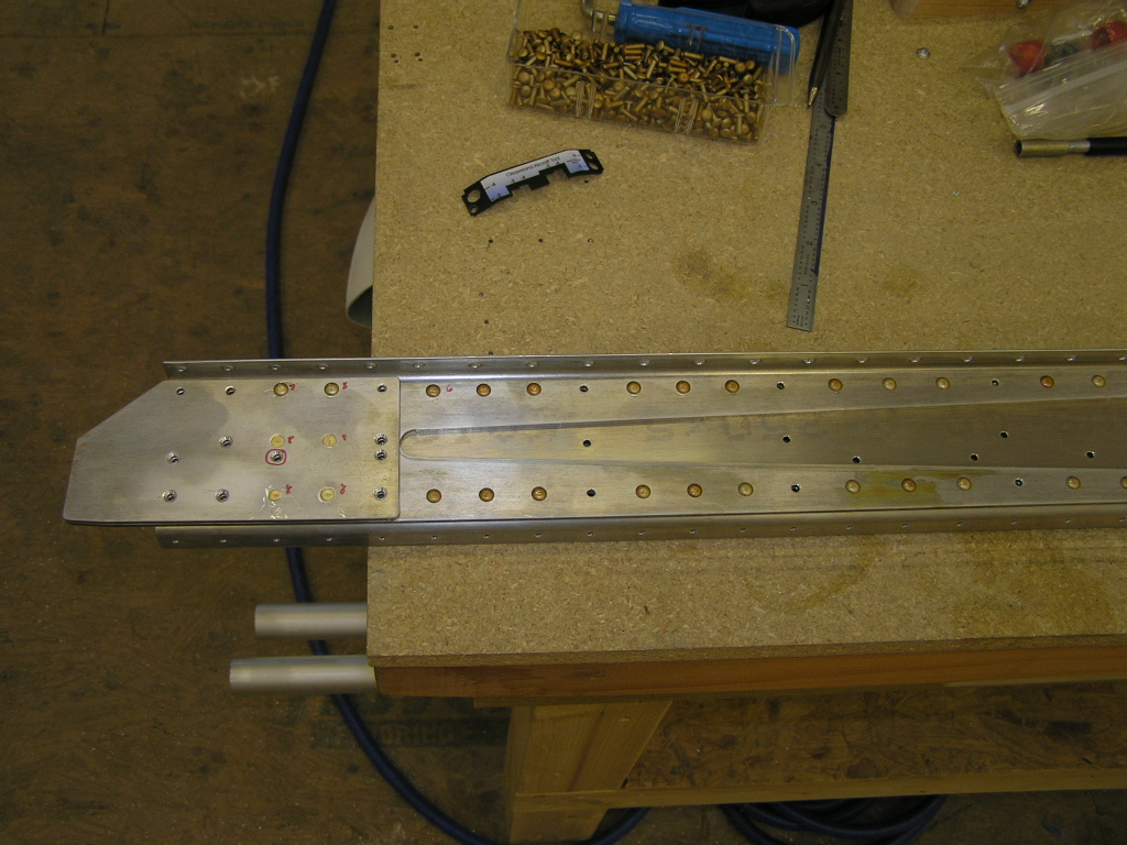 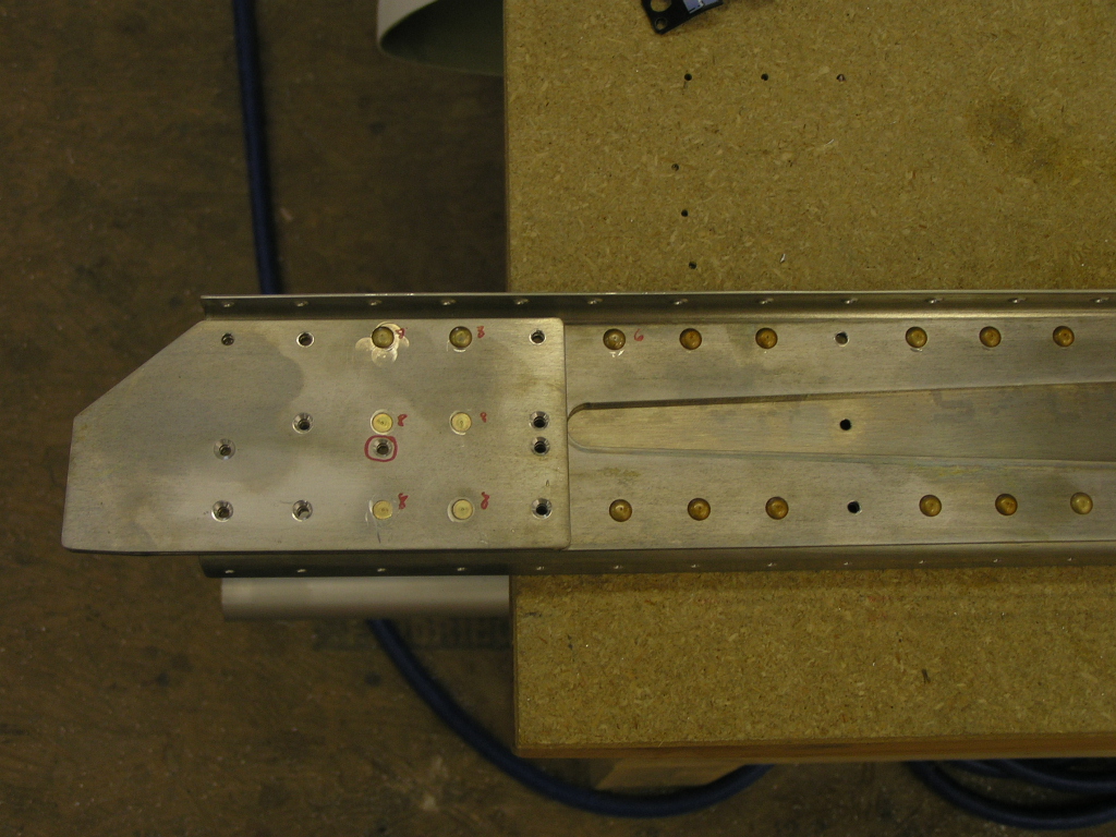 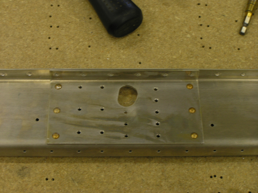
You will notice I deviated from where the plans say to
countersink the 3 holes at the spar end. The doubler plate
is too thin to countersink so I countersunk the spar and dimpled
the doubler plate. Hope Van doesn't care. Got started on deburring the nose ribs. I deburred the flanges using the
scotchbrite wheel on the grinder. I deburred the holes
using a 1" scotchbrite wheel in the die grinder. Finished
the nose ribs. |
6.0 |
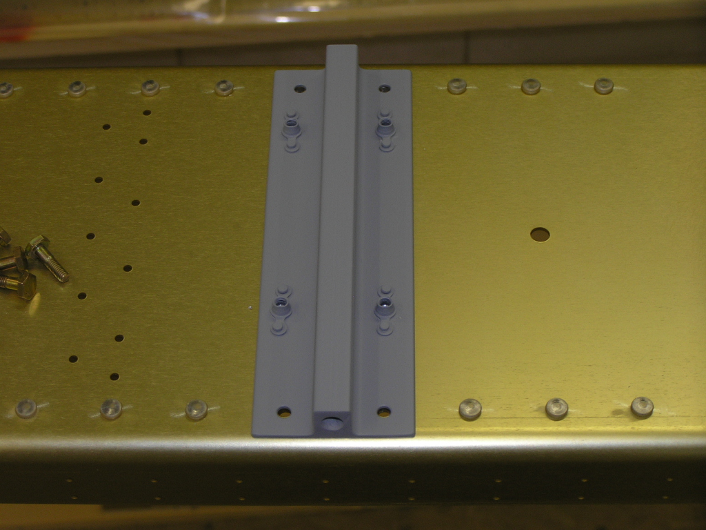
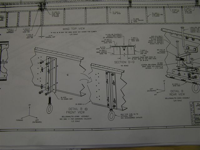
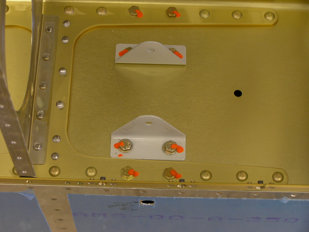
| 8/5/06 | This evening I tapped the tie-down bars with the
3/8-16 tap I bought at Home Depot. It went exceptionally
well. I then bolted the tie-down bracket to the main spar
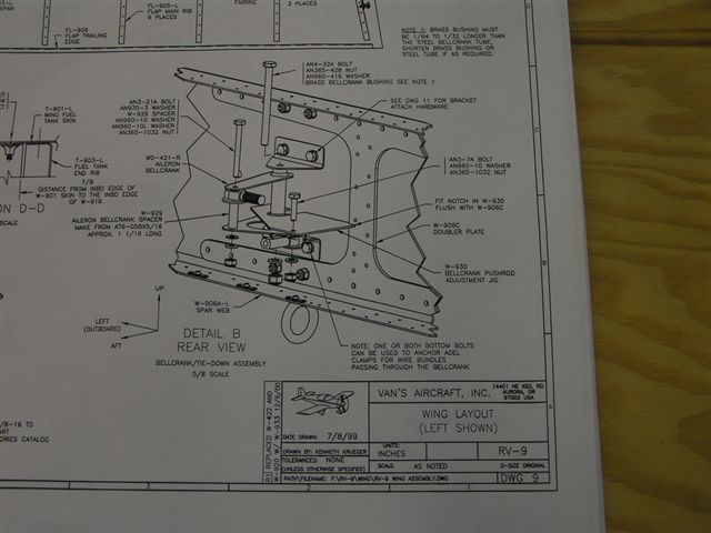
and torqued. I then bolted the aileron bellcrank brackets. 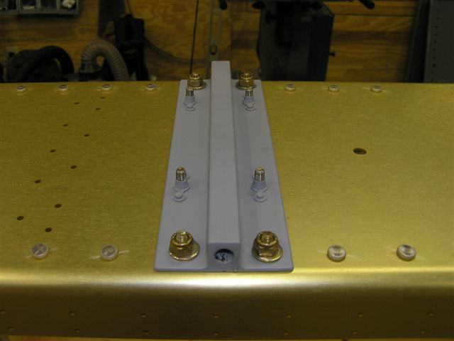
One point here. The plans in DWG 11 & 9 show the nuts for
the tie-down bracket on the fore side of the spar but DWG 10
shows the bolts on the aft side of the spar...Not sure if it
really matters, guess I'll find out down the road. |
2.0 |
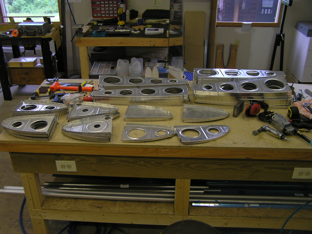
| 8/6/06 | More deburring of ribs. I worked until the
temp in the shop hit 90º
(1:00pm). Later, I continued deburring. I went ahead
and made the aileron alignment tool from a scrap piece of
aluminum angle I had.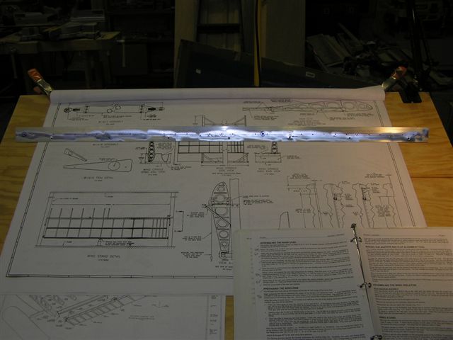 |
3.5 |
| 8/8/06 | Finished deburring...Started fluting | 1.5 |
| 8/9/06 | ...and fluting... | 1.5 |
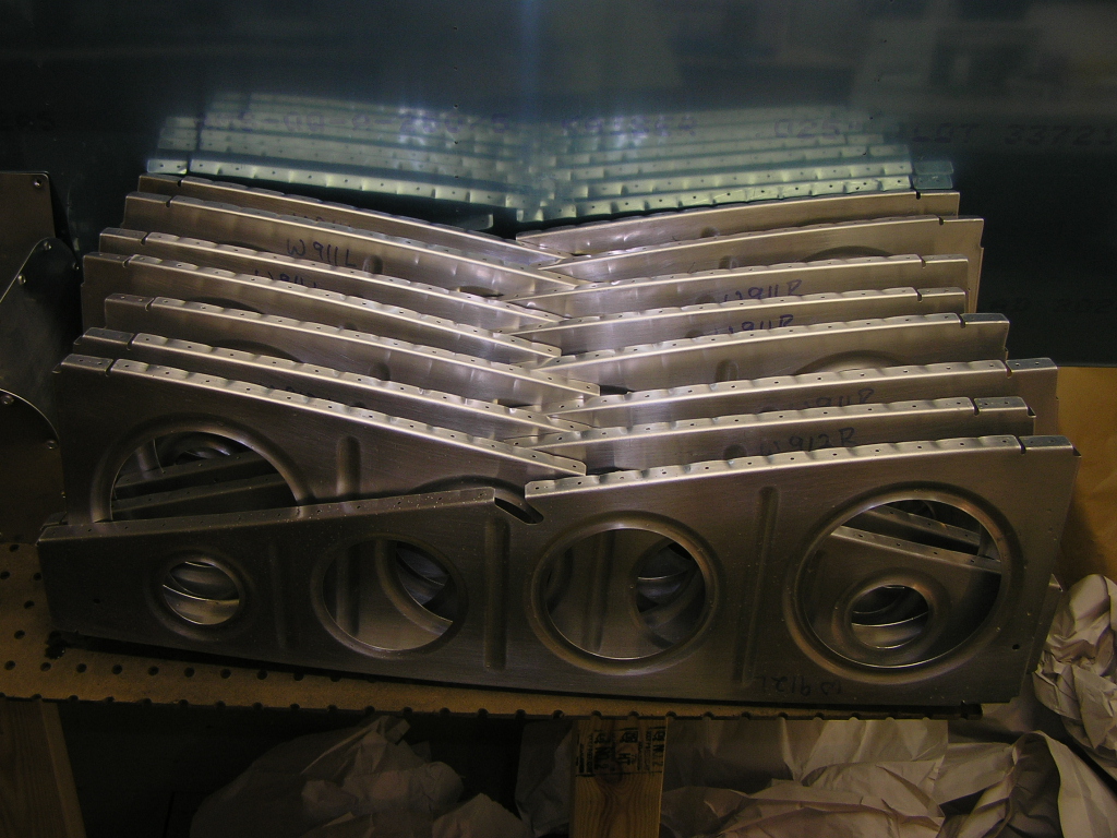
| 8/11/06 | ...and more fluting. Finally completed deburring and fluting all the wing ribs. Started clecoing the W-910, W-911 & W-912 wing ribs to the main spar. | 3.0 |
| 8/12/06 | Match drilled the main ribs to the main and rear
spars. Took it all apart and deburred the spars and ribs.
Started the process to chemically treat the main ribs.
This is a three-step process: 1) scuff the parts with a
scotchbrite pad and soapy water; 2) Chemically etch/clean the
parts using SanChem (Part C) cleaner; 3) Chemically treat the
parts using SanChem (Parts A & B) converter. Rinse with
water and rivet! |
5.0 |
| 8/13/06 | Worked most of the day treating the ribs.
It would be MUCH faster to simply clean the ribs and shoot them
with a self-etching primer but then you have a coating that can
scratch off and adds significant weight. I figure that I
will save about 2 pounds per wing by chemically treating the
ribs as opposed to conventional priming....And have better
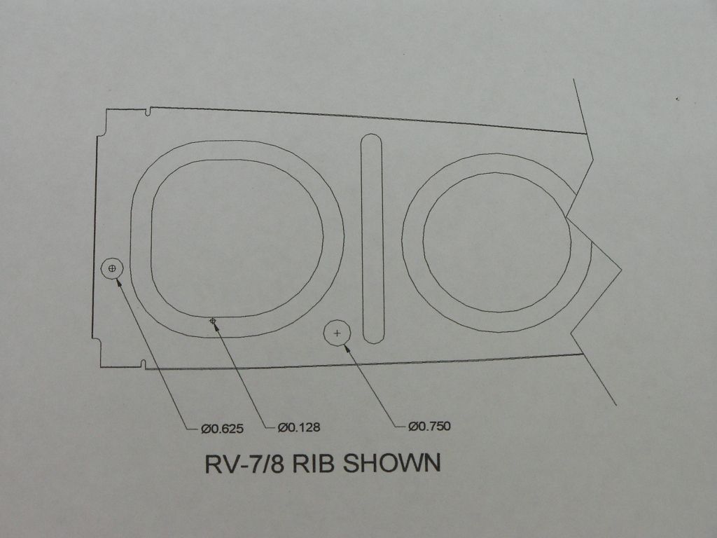
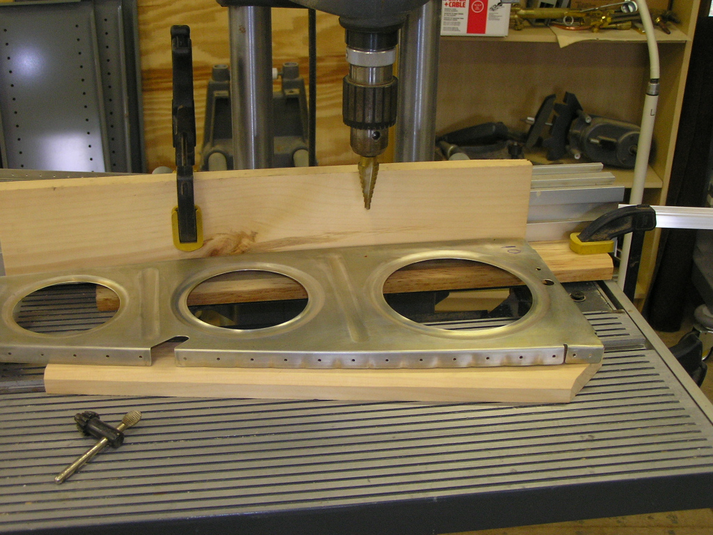
protection to boot! I decided to drill a 0.75" hole in each
wing rib to accommodate the wire conduit. This will
provide plenty of access for wiring for the wingtip landing
lights, strobe, nav light, under-wing LED, A/P servo as well as
possibly a wingtip antenna. Next, I applied 3M tape to the main spar to protect the
anodized finish when I rivet the ribs. Finally, I clecoed the ribs to the main spar then clecoed the
rear spar. I will rivet the ribs on the bench for easier
access then transfer the assembly to the wing stand. |
7.0 |
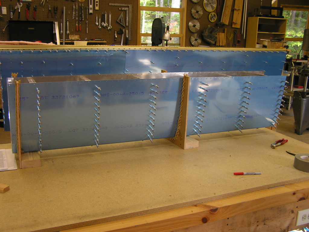
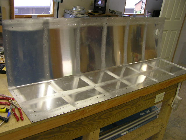
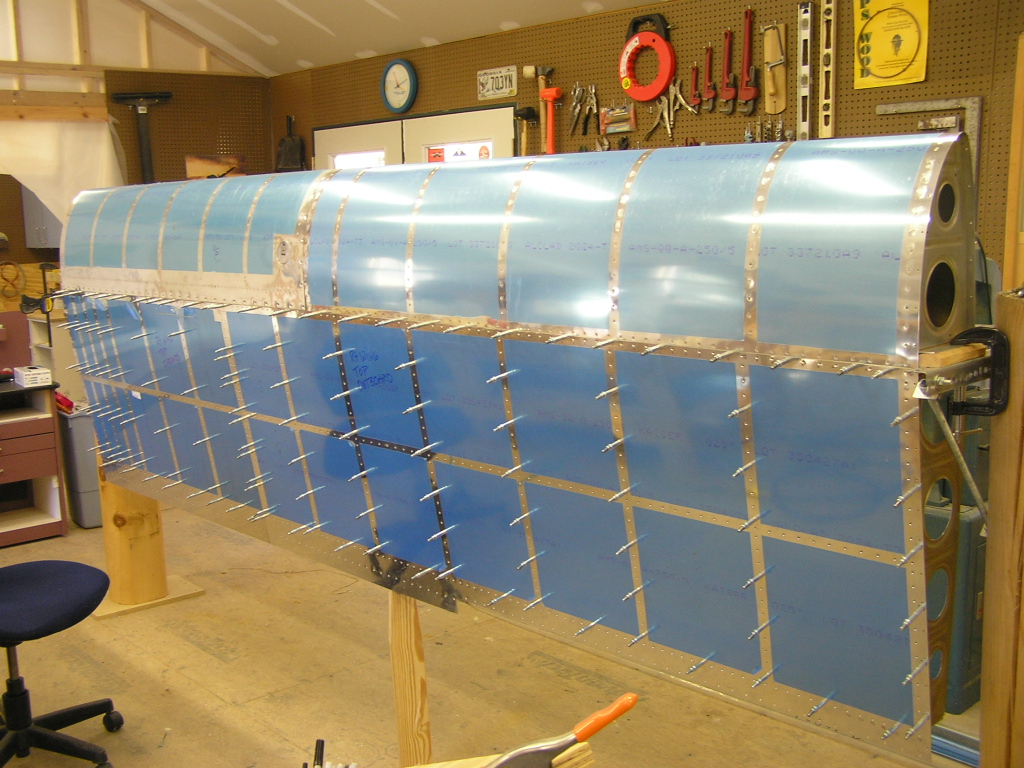
| 8/17/06 | Riveted the ribs to the main spar. Riveted
the ribs to the rear spar. Cut a piece of 1.5 x 1.5
aluminum angle and bolted it to the end rib. Hung the
right wing on the wing stand and clamped the wing down. I
cut a 1x4 to brace the middle of the wing and placed it under
the rear spar. Next, I dug out the W-927 wing walk doubler
and placed it under the W-902 inboard top skin. I match
drilled the holes in the doubler as specified in the plans.
Next, I clecoed on the W-902 & W-903 top skins and the doubler
plate.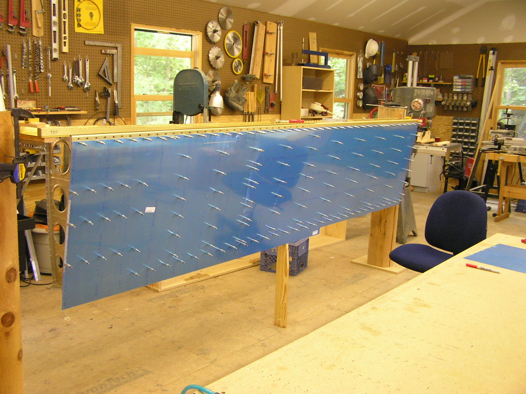 |
4.0 |
| 8/18/06 | Match drilled the top skin. Cut the W-926A/B J-stringers to length and deburred. Had a visit from a fellow EAA 1211 member, Anton D'Allen. Anton owns a Cessna 150 which he keeps at Martin Campbell airport (1A3). I would have accomplished more but because of the hot weather and lack of rain, the Forestry Service emptied the three trout hatcheries in the Toccoa River, I called Lynne and this afternoon we went fly fishing. Three hours later we were eating fresh grilled trout. It doesn't get any better than this. | 4.0 |
| 8/19/06 | Installed and drilled the W-926A/B J-stringers.
Clecoed on the W-904 & W-905 bottom skins. Match drilled
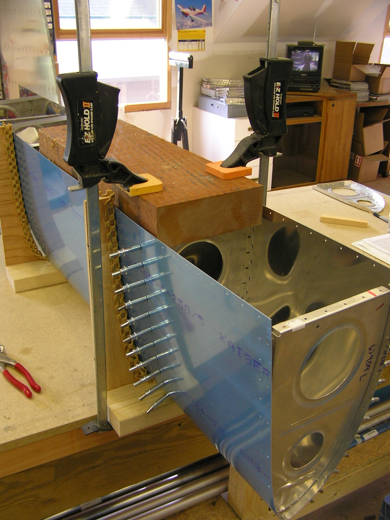
and then removed. 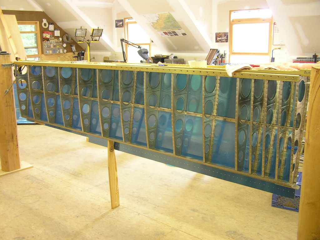 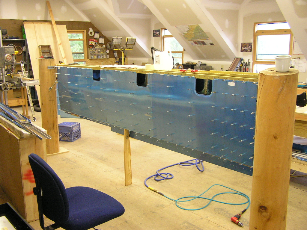  I went ahead and drilled the wiring conduit holes in the ribs for the left wing since I had the jig set in the drill press. I cut my cradle I had made for my horizontal stabilizer to
fit the leading edge and tanks. I inserted the skin and
began clecoing the ribs. The bottom went well but trying
to cleco the top rib holes was impossible. After much head
scratching I resorted to using clamps. I used a block of
wood and the holes lined up perfectly. I mounted the leading edge on the wing stand and clecoed it
to the spar. I fabricated the W-919 Doubler strip and
"worked" it until it was properly aligned between the W-901 skin
and the W-908 rib. I then match drilled the holes and
clecoed. |
7.0 |
|
Total Hours |
69.2 | |
| Right Tank | ||
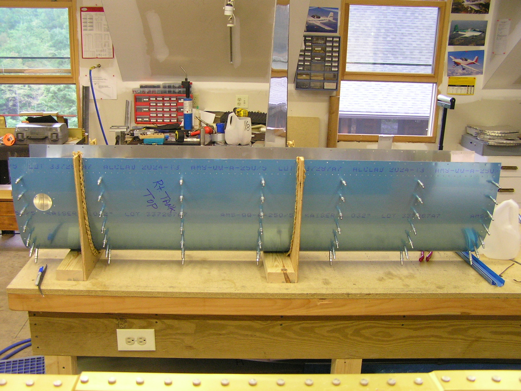
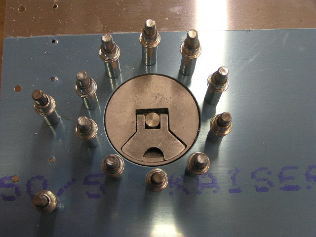
| 8/20/06 | I will need to order some more 3/32 clecos as
well as a few 3/16 clecos. I opened up the capacitive
senders and tried to get an idea how they will go in the tanks.
The plans come with a full-scale drawing so it should be pretty
straightforward.
I put the right tank skin in the cradle and clecoed the ribs.
I had to use my board and clamping technique in order to get the
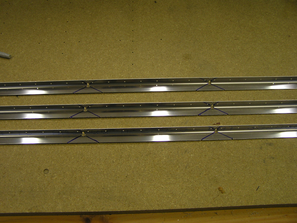
clecos in but it worked. Next, I trimmed the T-911 and
T-911-INBD stiffeners, deburred and match drilled them to the
tank skin. Next, I carefully oriented the attach angles on the rear
baffle. Then, using the W-932DG drill guide, I drilled
each attach angle. I enlarged the 1/8" holes in the specified angles to 3/16". I drew a line using the 1/8" hole as a guide then clecoed the attach angles to the baffle and match drilled. |
6.8 |
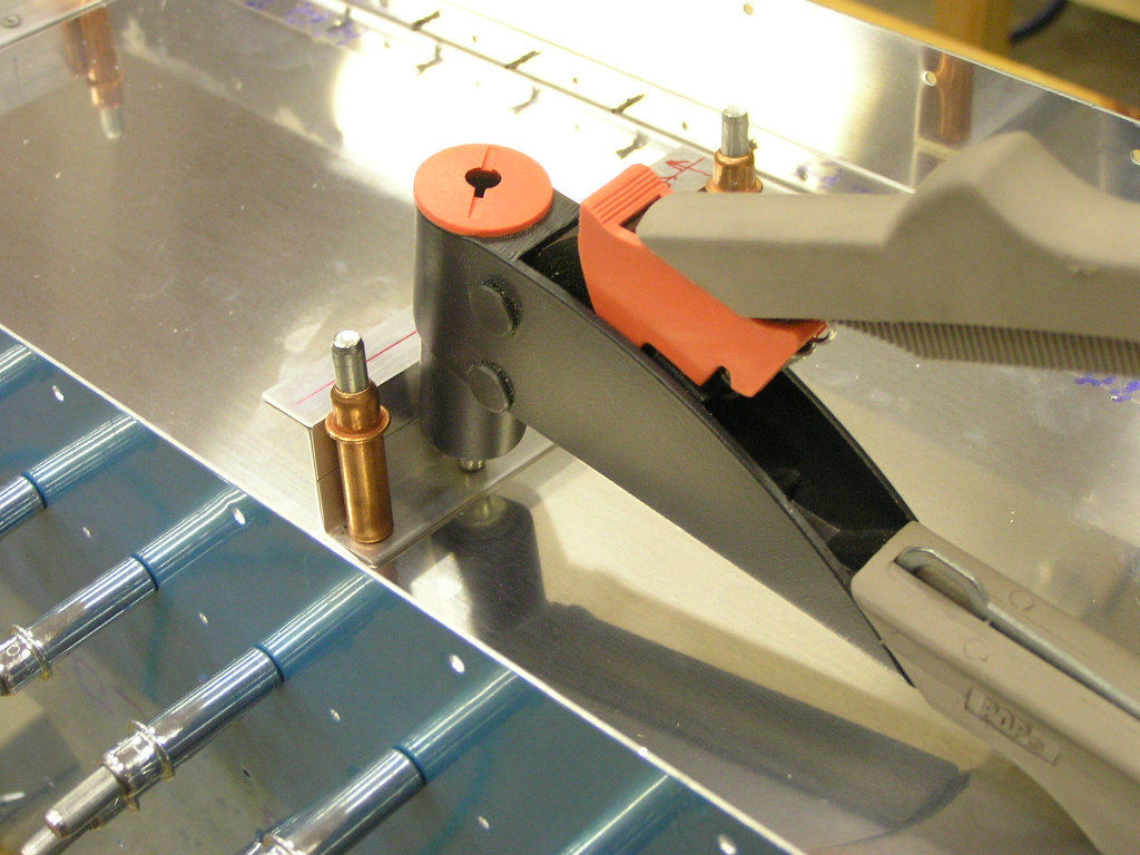
| 8/25/06 | Today I received the pre-fabricated fuel pick-up
tubes that Van's sells. Thanks to
Bill
Repucci for the heads-up!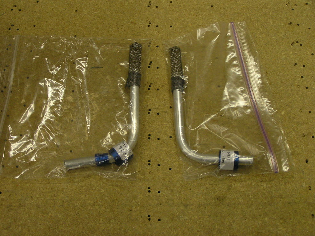
Pop riveted the attach angles to the baffle. I had to
grind down the head of my pop rivet gun in order to set the pop
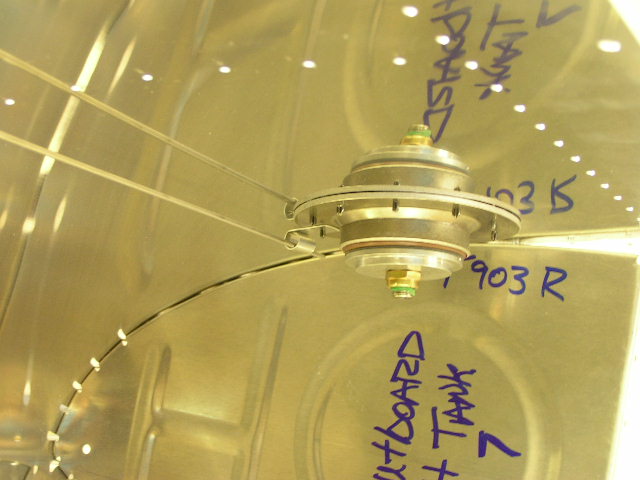
rivets in the attach angles. Placed the tank on the spar and clecoed the T-901 tank skin
to the spar. Using 3/16" clecos, I attached the attach
angles to the spar and match drilled the attach angles. I checked the wing for twist by hanging a plum bob with monofilament from the main spar at each end of the wing. Measuring from the rear spar, the wing alignment is within 3/32. Good enough! |
3.0 |
| 8/26/06 | Removed the tank from the spar and placed back
in the cradle. Drilled all the holes to final size.
Countersunk the rivet holes in the W-901 skin where it will
attach to the baffle. Drilled the spar attachment screw
holes to final size (#19).
Removed the attach brackets from the baffle by drilling out the
pop rivets. Drilled the attach brackets for K1000-3
platenuts. Countersunk the brackets and washed down with
MEK. Primed the brackets with SEM self-etching primer.
Attached the K1000-3 platenuts to the spar. Riveted the
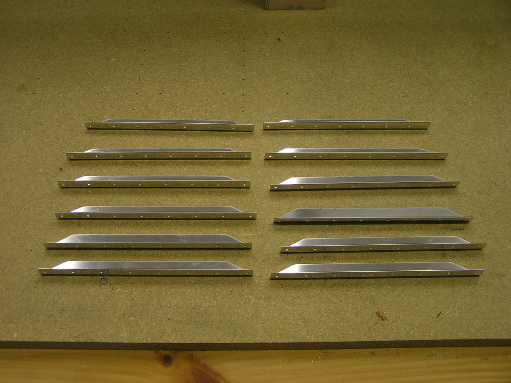
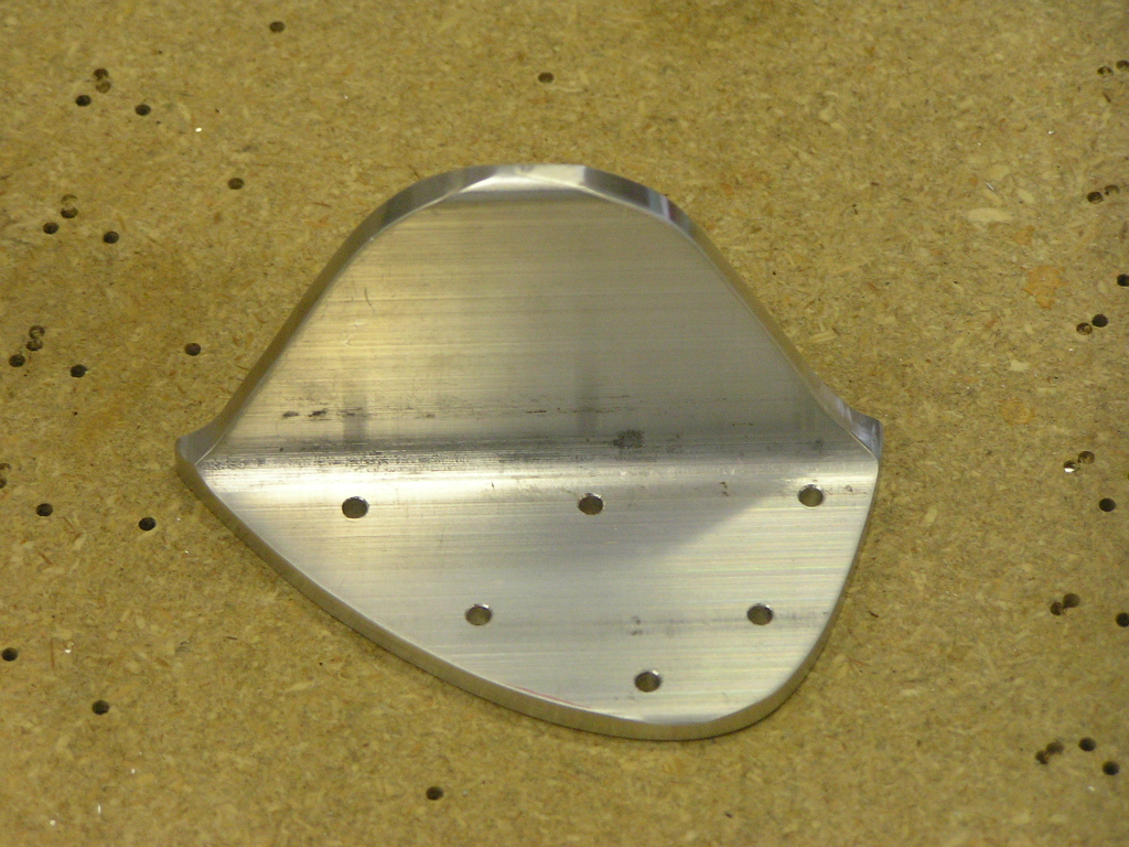
platenuts to the attach brackets. Fabricated the T-905 attach angles by first tracing the
pattern on to a piece of paper and cutting out the pattern.
I then transferred the pattern to the piece of aluminum angle.
I also marked out the pattern for the left tank. I then
rough-cut the angles using the bandsaw. I used the bench
grinder and oscillating drum sander to finish trim the angle.
I match drilled the attach angle to the inboard rib. |
7.0 |
| 8/27/06 | Fabricated the T-410 reinforcement plates to the
inboard and outboard ribs. Match drilled the T-410 to the
inboard rib. I assume the outboard plate will be attached
to the rib with proseal.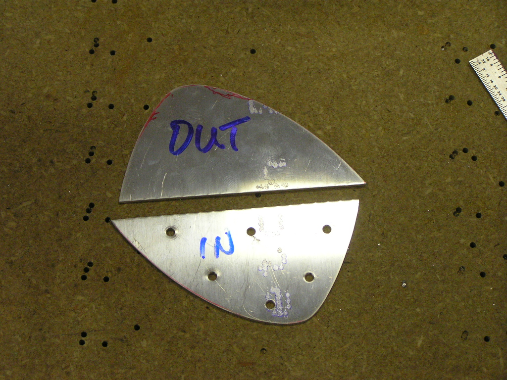
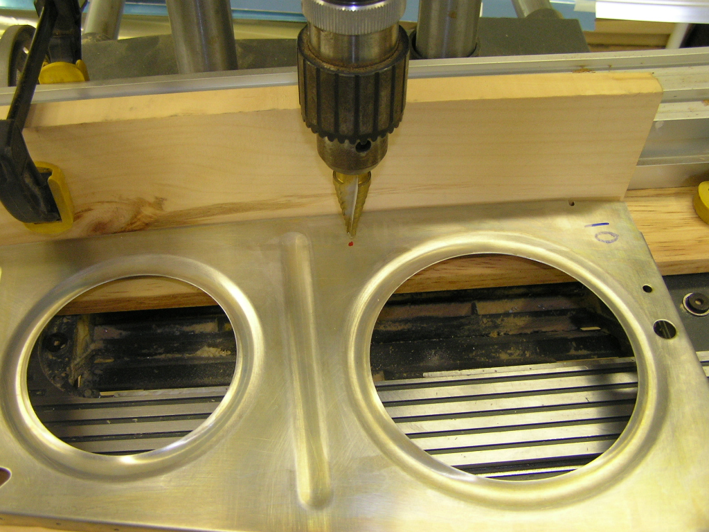
Capacitive Senders: I match drilled the capacitive
sender plates to the second and sixth ribs per the plans.
I also drilled the notch in the snap bushings. Drilled the
3/8" hole for the BNC connector in the inboard rib.
Riveted the platenuts in the capacitive plates. I will
wait for final install after the ribs are prosealed and before
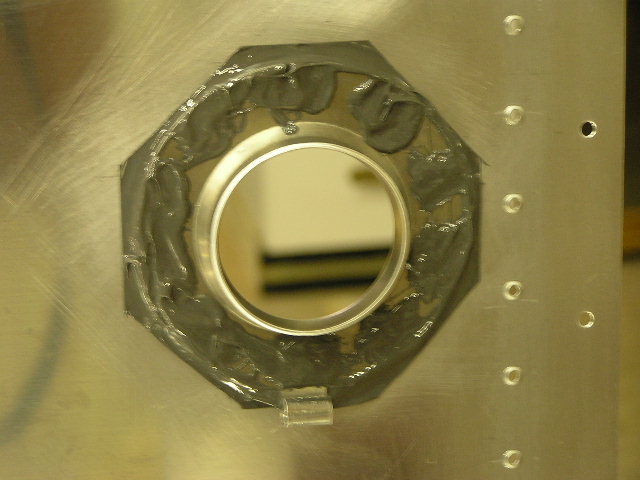
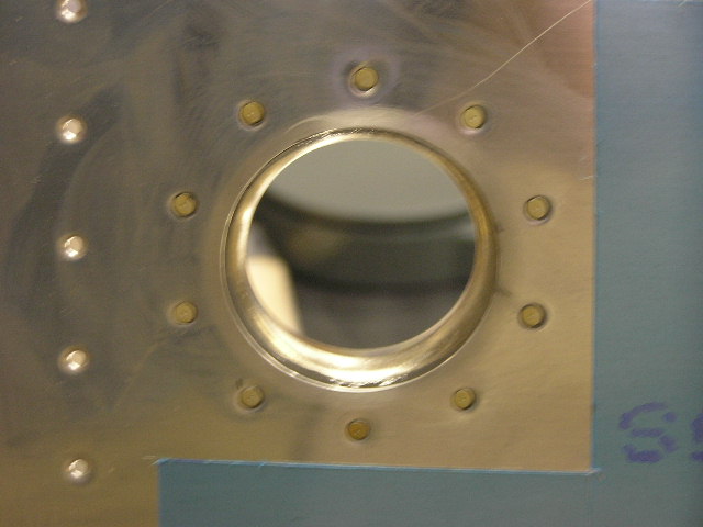
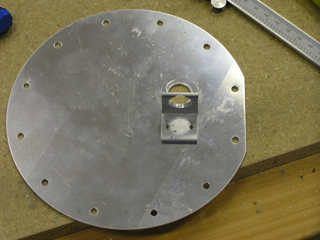
the baffle goes on for good. Used the fly cutter to cut the access hole in the inboard
rib. Match drilled the T-411 plate using the T-407
stiffener ring for the platenuts. Deburred and countersunk
the T-407 and riveted the platenuts. Drilled the hole for
the fuel pick-up since the T-411 plate did not have it
pre-drilled. Fit and drilled the T-406B fuel cap flange. Deburred
and countersunk the flange. I also fabricated the T-914
clips from a scrap of .020. I used a piece of hinge pin to
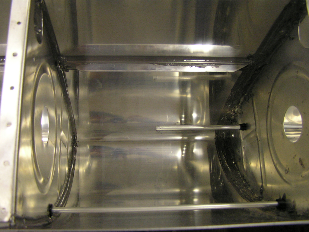
check the alignment for the clip. Fit and match drilled the VA-112 drain flange. I'm still trying to determine how I want to plumb the
fuel/vapor return line in the tanks. I have seen how
Brad Oliver did his on his RV-7, but the inboard rib on the
-7 is different than the -9. I will be seeking advice on
this while I wait for my fuel fittings to arrive. Here is
my current idea... |
7.0 |
| 9/1/06 | Disassembled tank and deburred stiffeners and ribs. | 2.0 |
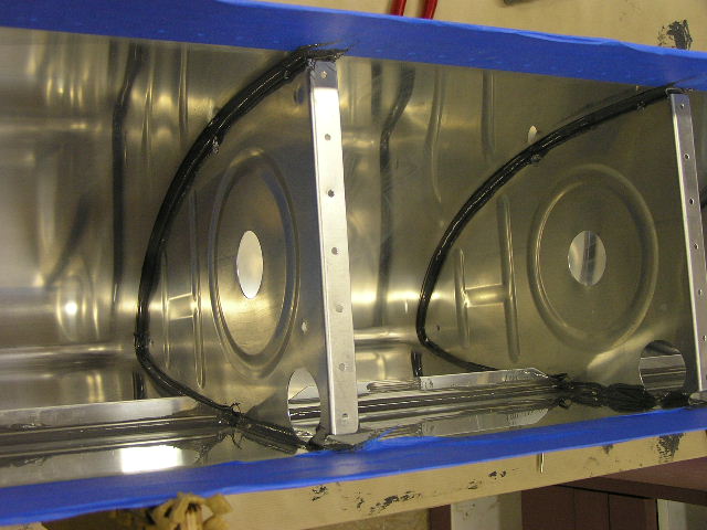
| 9/2/06 | I decided on a location for the fuel return and
drilled the holes in ribs #2 and #3 for the fuel return line and
deburred.. The line will run to the third bay.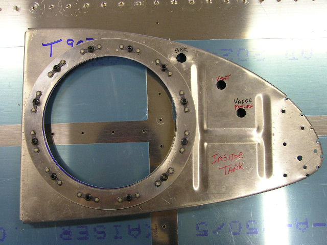
Deburred skin. Fabricated the small plate for covering the
tooling hole in the outboard rib. Drilled and deburred
cover plate. Dimpled tank skin and stiffeners. Prepared tank for prosealing stiffeners. Out of all the
info I have read about the ProSealing process, they ALL
emphasized having a clean, organized work area before you
start... Mixed 10 oz. of proseal and back-riveted the stiffeners to
the skin. Prosealed and back-riveted the T-406B fuel tank flange and
vent clip to the skin. Prosealed and used the pneumatic squeezer to attach the
VA-112 fuel drain flange to the skin. |
9.0 |
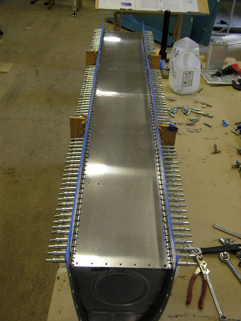
| 9/3/06 | Having survived my first real episode of
ProSealing, I moved on to the riveting of the ribs. I
placed the tank skin into the cradle and clecoed the ribs.
I taped off beside each rib leaving about 1/4" for the final
filet. 
I mixed up 5 oz. of ProSeal and mixed thoroughly. Skipping
the outboard end rib (#7), I removed rib #6, cleaned the skin
and rib thoroughly with MEK, applied a 1/16th" coat of proseal
to the skin, inserted the rib and clecoed every hole. I
then repeated the process on ribs #5 and #4 then I began
riveting the skin to the ribs. This is where it really got
messy. I would pull a cleco, insert a rivet, set the rivet
then repeat on the other side. By the time I finished
riveting all three ribs and started covering the shop heads of
the rivets, the proseal was really starting to set-up (3-hours).
I was able to extend the pot-life of the proseal by
refrigerating it before mixing. Although the shop temp was about
78º, I got over 3- hours of workable time. I also think I will
re-hit a couple of areas when I mix the next batch of proseal
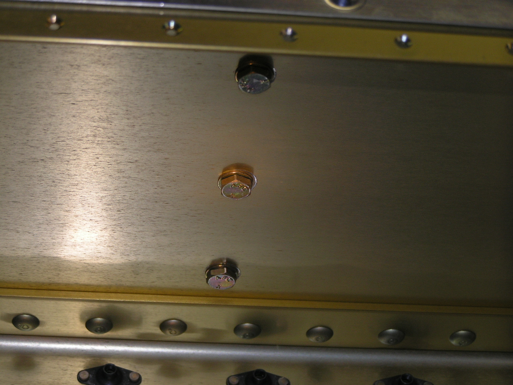
just to be on the safe side. I had a rivet that appears to be split. This is
possibly from over-driving it with the rivet gun. I'm
gonna get a couple of opinions as to whether I should drill it
out or let it alone. |
6.2 |
| 9/4/06 | I went ahead and drilled out the cracked rivet
with a 3/32" bit. I used the next-size-up rivet (4.0) and
flattened it a little using the pneumatic squeezer to make it a
little fatter. It went in nicely. I moved ahead and
prosealed and riveted ribs #2 & #3. Incidentally, I had
three rivets I was not happy with so I did the "drill-out
routine" again. I'm actually getting pretty good at this! After cleaning up, I worked on the capacitive senders by
soldering the 15-inch sections of 18 AWG wire to the BNC
connectors. I also cut two 46-inch sections and crimped
and soldered ring connectors on one end. The wiring for
the cap senders will have to be completed during final
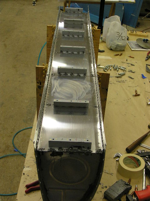
installation of the tanks. I went ahead and mixed up another batch of proseal and
riveted the inboard and outboard ribs. I also prosealed
and riveted the T-905 attach angle and the T-410 reinforcement
plates. Finally, I mixed up a small batch of proseal and
made sure to cover the shop heads of all the rivets and ensured
good filets. |
7.0 |
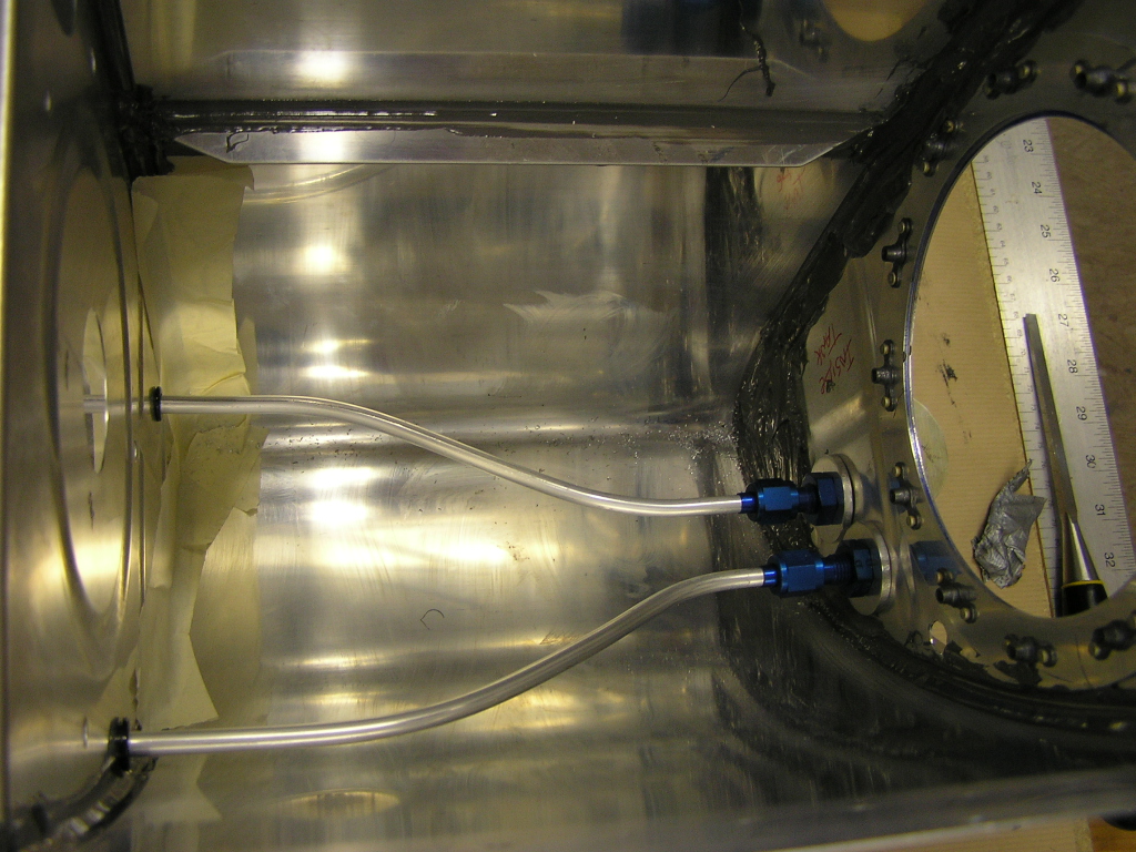
| 9/7/06 | Worked on the tank plumbing. I had to
clean the proseal splatter from the vent line holes in order to
get the snap bushings to seat correctly. Then I installed
the vent tube, bent the tube to mate with the fitting and cut to
length. I then flared the end and loosely assembled the
fitting and tube.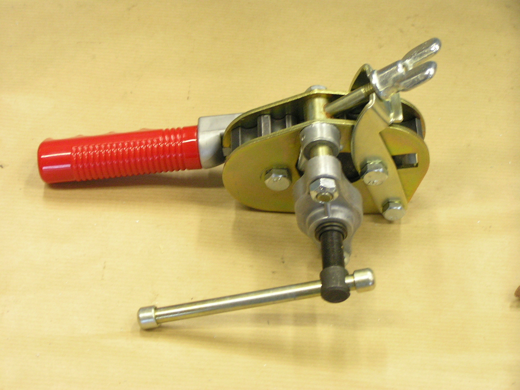 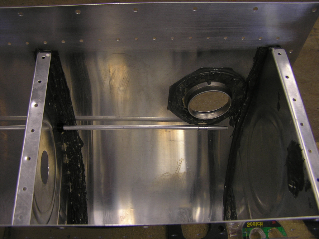
I repeated the process for the fuel/vapor return tube. I
decided to extend the tube to empty into the 3rd bay. This
should allow the warm return fuel to cool adequately before
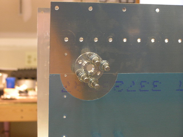
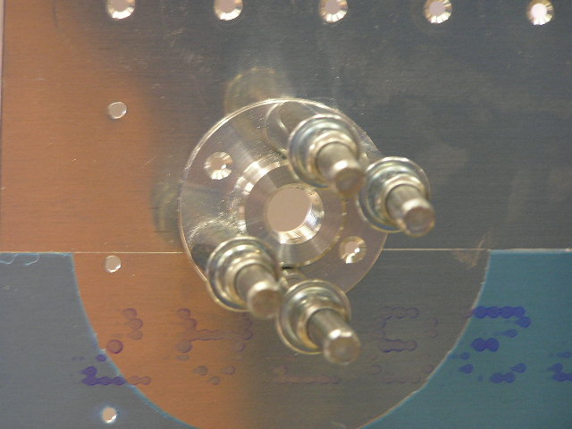
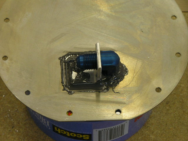
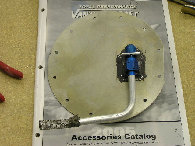
being drawn out again. I test fitted the fuel pick-up tube and fitting to the tank
access plate. This line and fitting is 3/8" where the vent
line and fuel return are 1/4". I fabricated the
anti-rotation brackets for both tanks, drilled the holes for the
rivets and deburred. I will need to prime the outside of
the tank access plate before riveting the anti-rotation bracket,
installing the fuel pick-up tube and safety wiring the tube. |
3.0 |
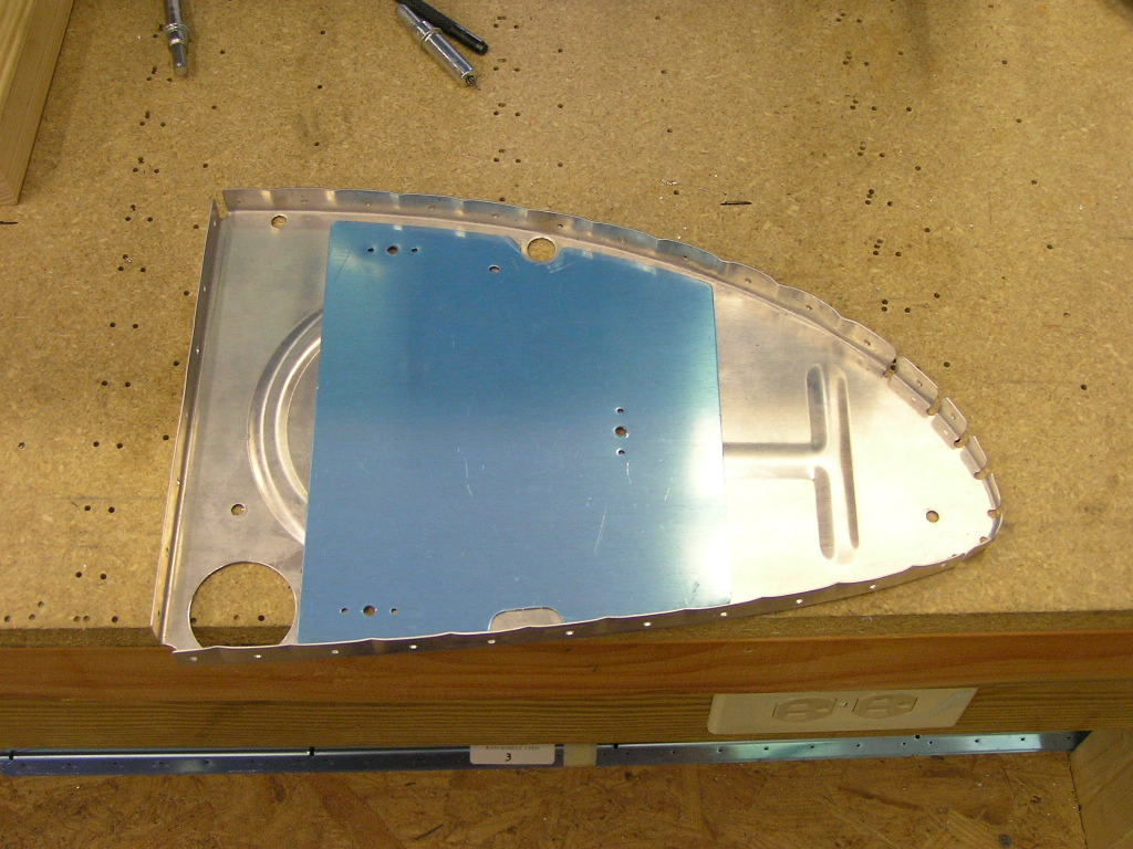
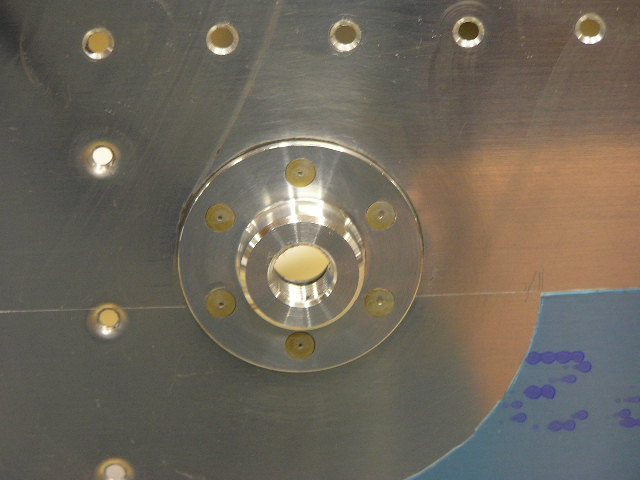
| 9/11/06 | Test fit the capacitive sender plates, ran the
wiring, crimped the wire nuts and final installed. I still
need to apply proseal on all the connectors. |
1.5 |
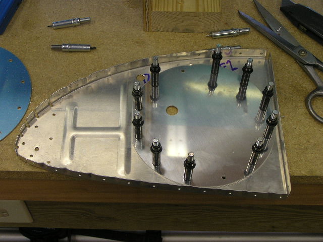
| 9/15/06 | Drilled the anti-rotation brackets to the tank
access plate and clecoed. Taped the tank in preparation
for prosealing the capacitive sender plates and plumbing.
|
2.0 |
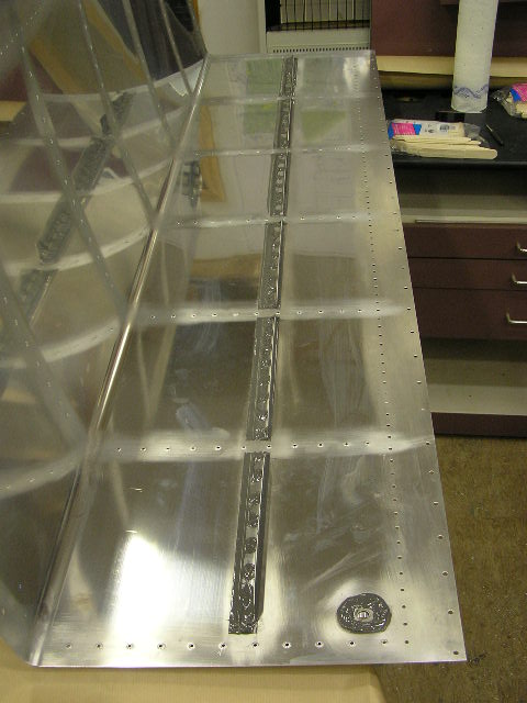
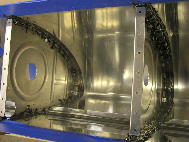
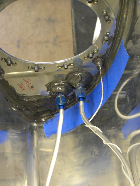
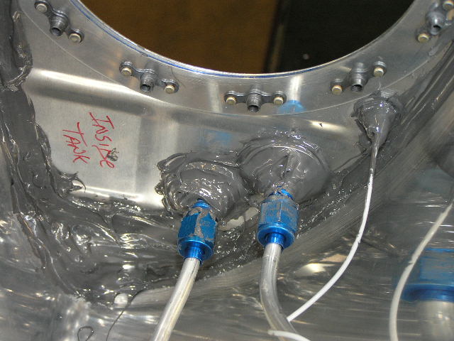
| 9/16/06 | Prosealed the electrical connections in the
capacitive sender plates.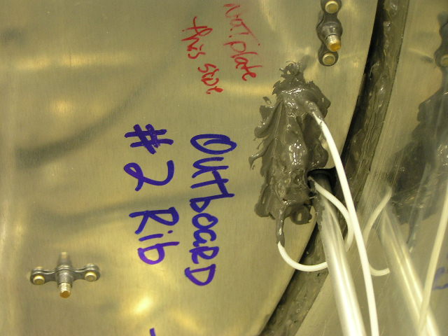 
Prosealed the plumbing fittings. I torqued the fittings for the tank vent tube as well as the
fuel/vapor return to 50 in./lbs. Riveted and prosealed the anti-rotation bracket to the tank
access plate and prosealed. Temporarily attached fuel pickup tube. Touched up
suspect areas inside the tank with proseal. Prosealed baffle and clecoed. Riveted baffle attach
brackets. Riveted the skin to the baffle. Riveting
the baffle took over two hours! I'm about ready to be done
with this tank. |
8.0 |
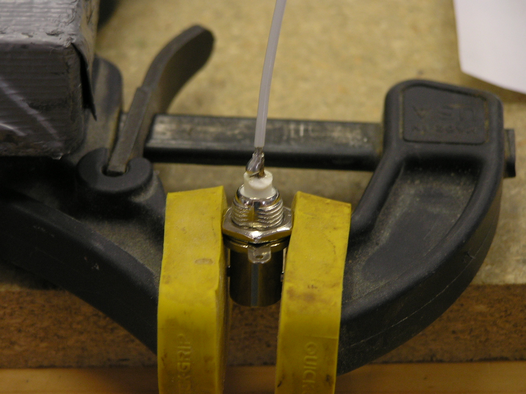
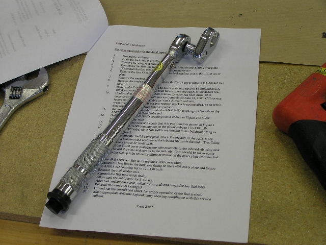
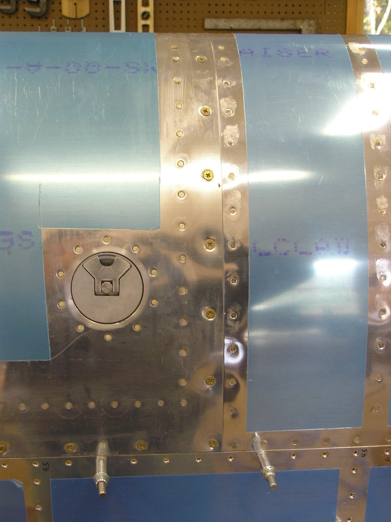
| 9/17/06 | I torqued the fuel pick-up tube nut to 110 in.
lbs. and safety wired the nut for the fuel sender per the Safety
Bulletin.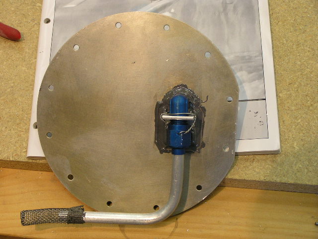
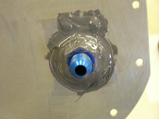
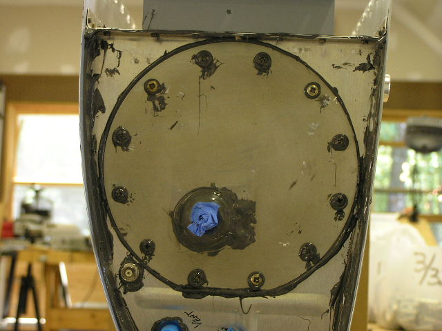
Prosealed the tank access cover plate. I omitted the cork
gasket per the recommendations of several other builders.
I swirled each screw in proseal before installing and
alternately tightened each screw. I like the nice uniform
squeeze-out around the plate. I had just enough proseal
remaining in the quart can to complete the tank. Right Tank is finished! Next weekend I will test for leaks. |
1.0 |
| 9/22/06 | I got the Van's Tank Test Kit and some balloons this week and tonight I hooked it all up and pumped the tank until the balloon filled. After swabbing the entire tank with soapy water and looking for bubbles, I can officially confirm it to be leak-free! | .5 |
|
Total Hours |
64.0 | |
| Closing Right Wing | ||
| 9/22/06 | Trimmed the plastic at the rivet lines on the bottom right wing skins W-904-R & W-905-R. Began deburring the bottom skins in preparation for dimpling. Used the die grinder with a 2" scotchbrite deburring wheel to grind the corner where the outboard skin overlaps the inboard skin. This will make a smoother transition where the skin meets the tank skin. | 1.5 |
| 9/23/06 | Dimpled the inboard and outboard bottom skins.
I removed the leading edge from the spar and disassembled.
Trimmed the plastic coating with my soldering iron.
Deburred the LE skin and ribs. Deburred the splice plate.
"Bo" checked up on me throughout the day... |
6.5 |
| 9/24/06 | Dimpled the splice plate. Dimpled skin and
ribs and set aside for chemical priming. 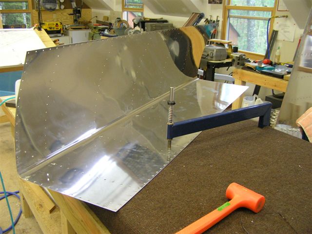 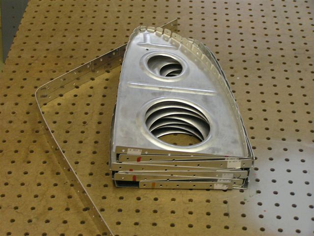
Removed the top outboard skin and removed the plastic along the
rivet lines. Deburred the outside skin. Removed the
inside plastic coating and deburred. Again, used the die
grinder with a 2" scotchbrite deburring wheel to grind the
corner where the outboard skin overlaps the inboard skin. |
7.0 |
| 10/1/06 | Dimpled the top outboard skin. Deburred the wing walk doubler. | 2.5 |
| 10/6/06 | Dimpled the wing walk doubler and deburred the
outer edges.
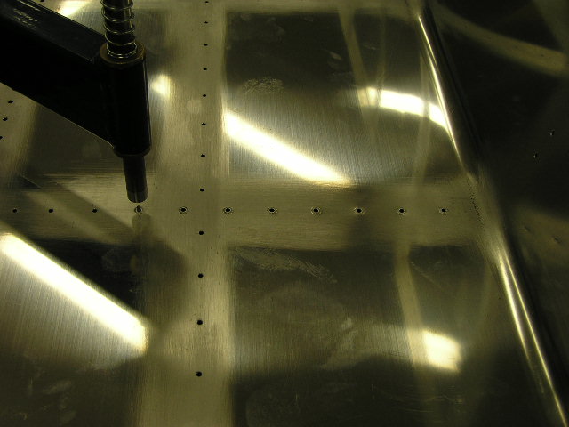
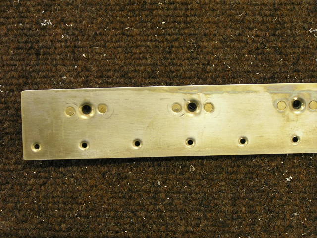
Deburred and dimpled the inboard top skin. Ground the corner where it is overlapped by the outboard skin at the junction with the leading edge. Deburred the outer edges. Deburred the main wing ribs and then dimpled. Used the deburring tool to ream the dimples in the rear spar (top and bottom). Drilled the #8 screw holes in the tank splice plate to full
size with a #19 drill bit. Deburred and dimpled.
Clecoed the K-1100 platenuts and drilled the attachments to #40.
Deburred and dimpled. Countersunk the platenuts. Set
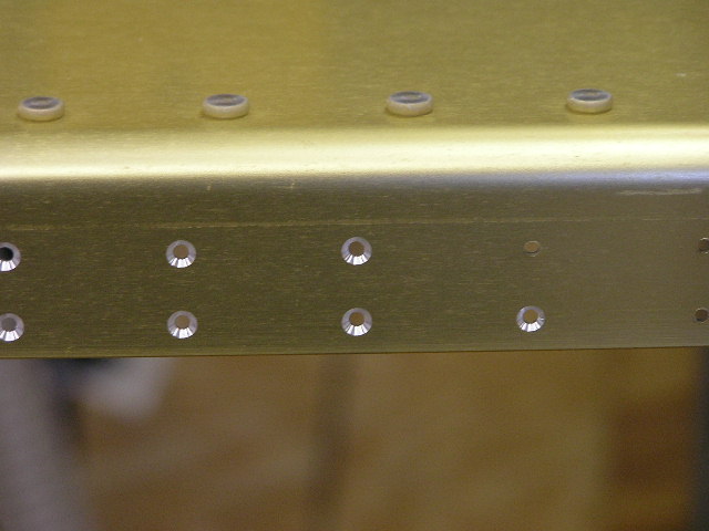
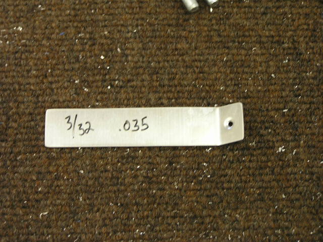
splice plate aside for conversion coating. Began countersinking the #40 holes in the spar. I
checked the depth occasionally using a dimple test set.
.035 for inboard skin and .025 for outboard skin. |
6.0 |
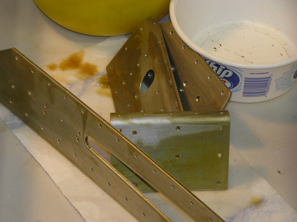
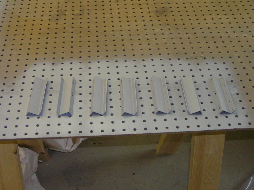
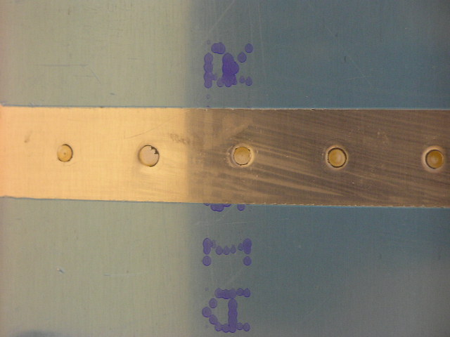
| 10/7/06 | Today was an absolutely breathtakingly beautiful
day so I set up some sawhorses outside the shop to chemically
treat the skins and ribs, etc. This is a tedious task that
involves cleaning the part with MEK, chemical cleaning and
finally chemical conversion coating. I treated the inboard
and outboard top skins, the outboard leading edge skin and ribs,
the wing walk doubler and the inboard and outboard J- stringers.
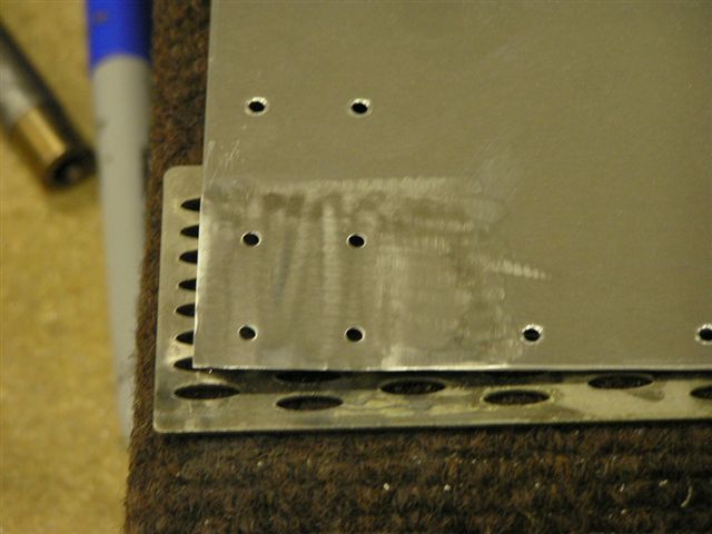
Here you can see the ribs before and after. I riveted the platenuts to the tank splice plate. I
used the deburring tool to ream out the dimples in the splice
plate in order to help make the leading edge skin, splice plate
and inboard end rib fit together as tightly as possible.
Placed the leading edge skin in the cradle and clecoed the
splice plate. Finished countersinking the rivet holes on the top spar
flange. |
6.0 |
| 10/8/06 | Today I began by assembling the ribs in the
leading edge assembly 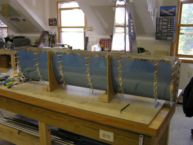
I finished countersinking the rivet holes in the spar flange and
used a q-tip to dab alodine in each countersink. This was
tedious and time consuming and I could have just taped the spar
off and shot with rattle-can primer but decided my wings are
going to be "primer-free". Besides, alodine offers much
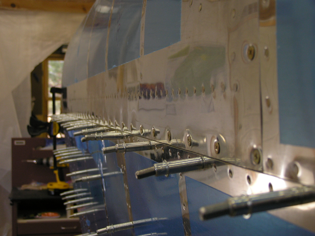
better protection. With this accomplished, it is now time to start riveting this
wing together! I started on the leading edge by using the
pneumatic squeezer to squeeze the aft two rivets on each rib top
and bottom. I then switched to the rivet gun and drove a
rivet in each rib on top and then on bottom. This "going
round and round is really slow but that's how the plans say to
do it. TIP: I found that the -4 rivets called out for
the inboard rib (and splice plate) were a little too short so I
substituted -4.5 rivets and they worked great. I got about 3/4ths of the rivets driven. |
4.0 |
| 10/11/06 | Finished riveting the leading edge and clecoed
it to the spar.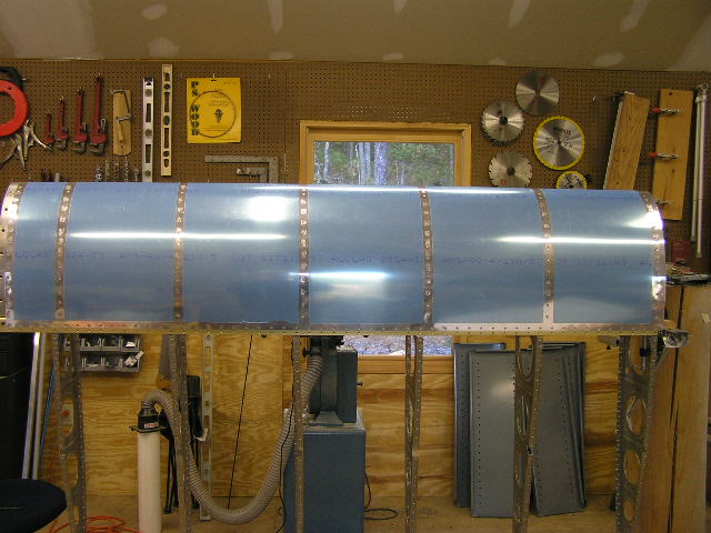 |
2.0 |
| 10/12/06 | Began riveting the leading edge ribs to the
spar.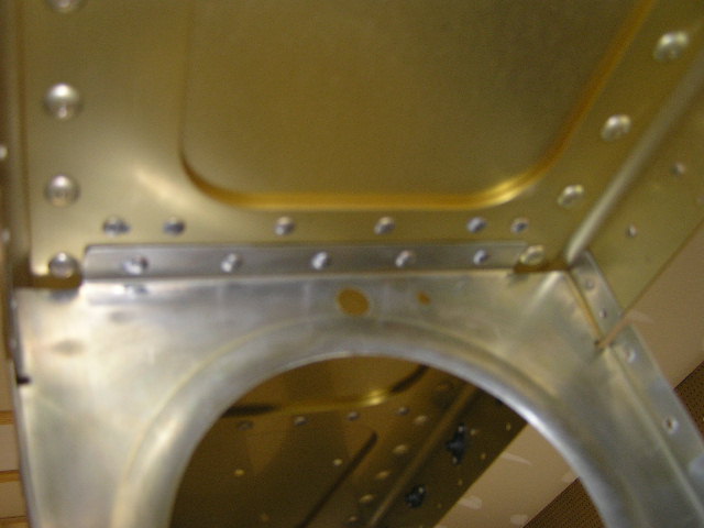 |
1.0 |
| 10/13/06 | Continued riveting the leading edge ribs to the
spar that I could reach by myself. There is still one bay
yet to rivet so I went ahead and squeezed the rivets along the
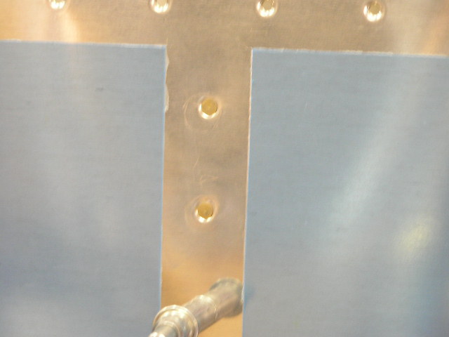
top and bottom spar.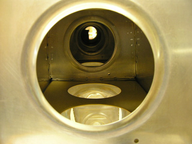 I drilled out the hole over the tie-down bracket to full size.
|
2.5 |
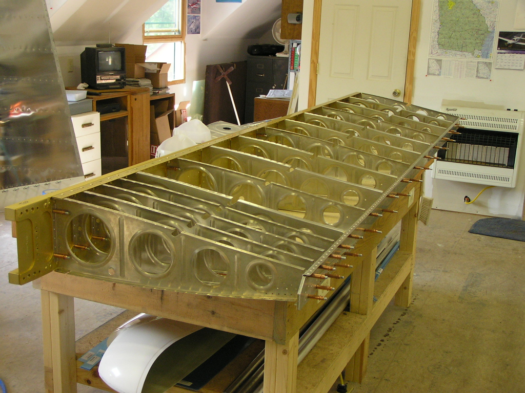
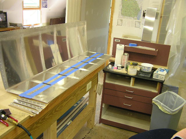
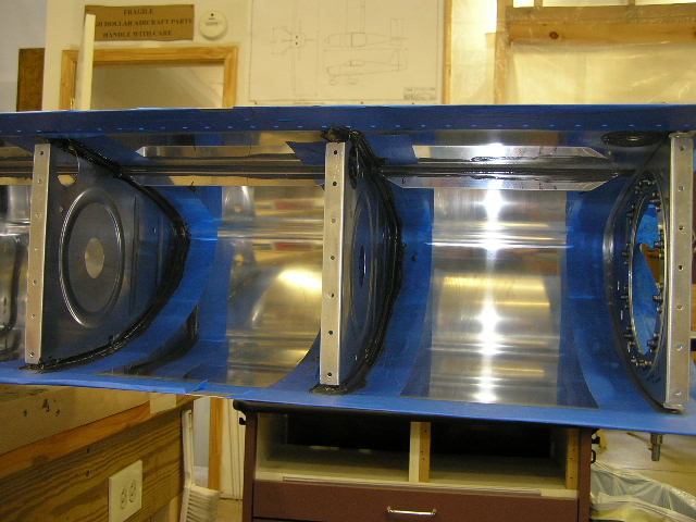
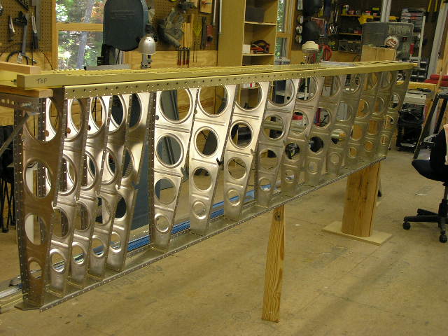
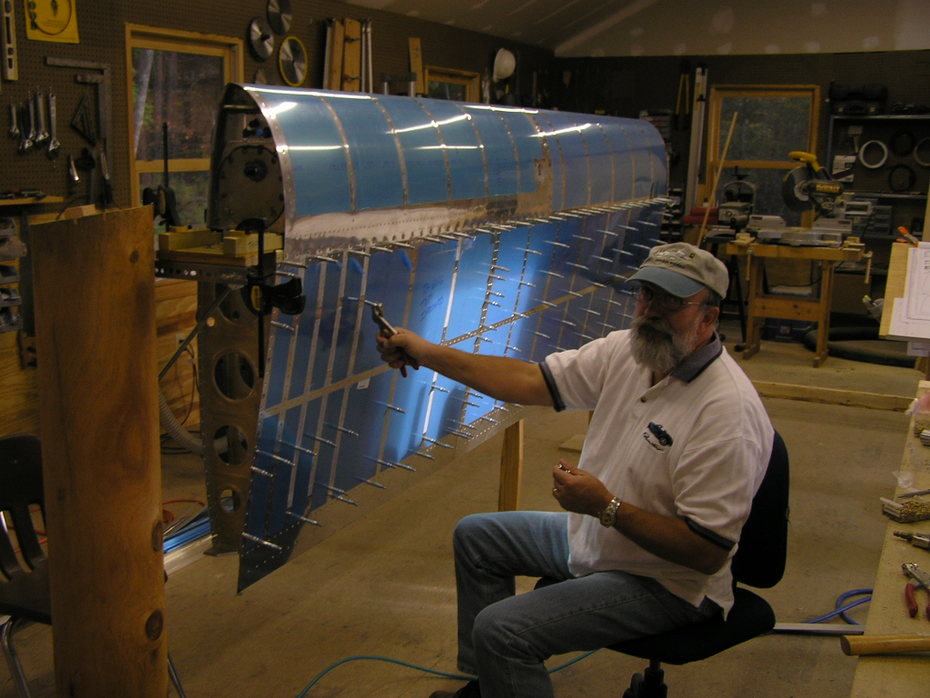
| 10/15/06 | I built the wing cradle per Van's plans.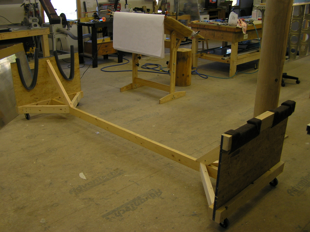 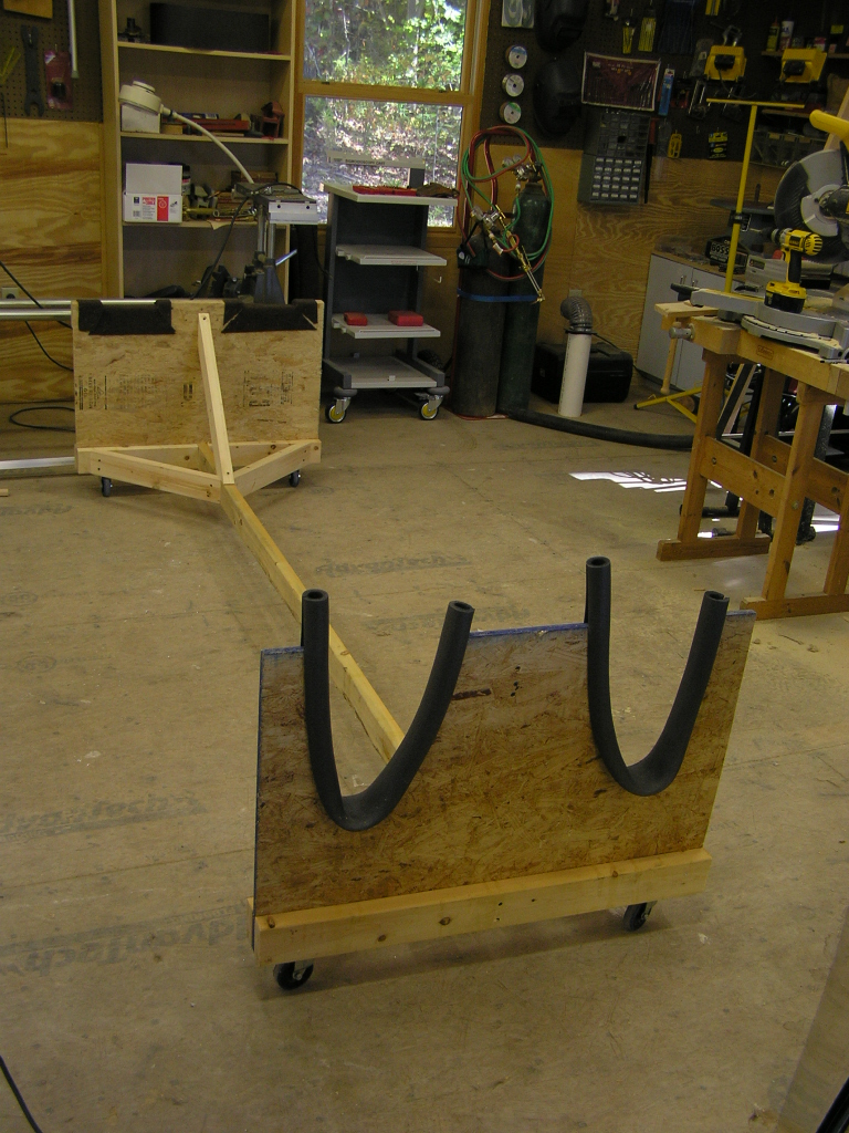
I got Lynne out to help me buck the last 5 rivets in the
interior of the leading edge. She has nice skinny arms. With this completed I was able to install the fuel tank and
torque the bolts through the spar as well as install the screws
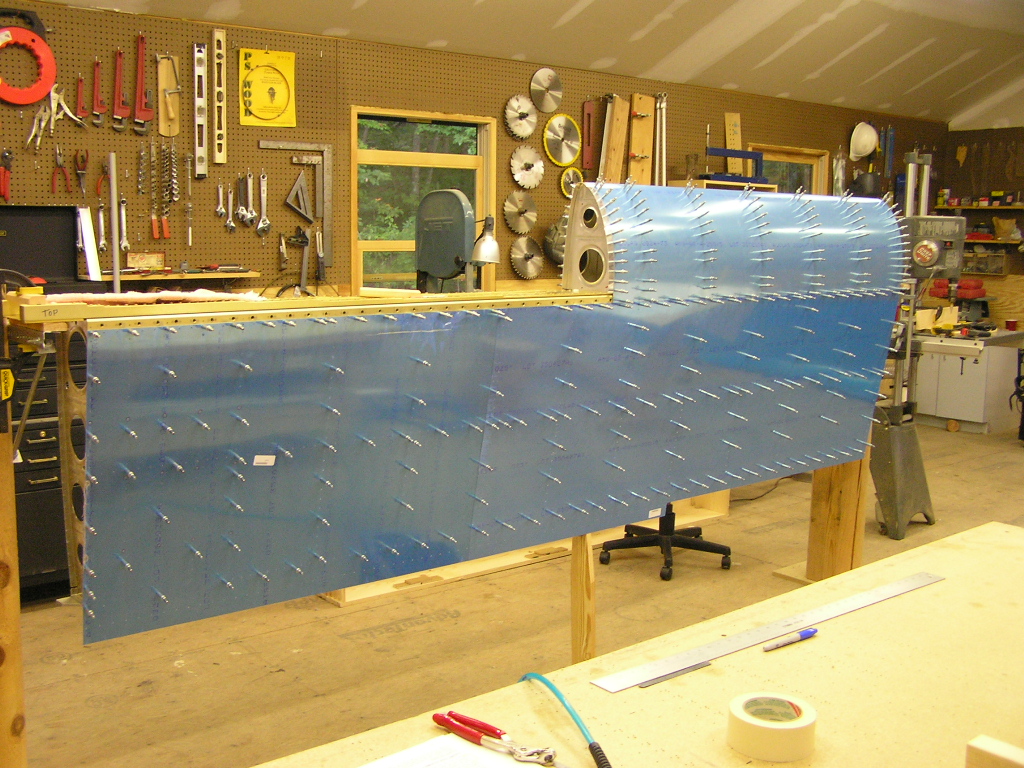
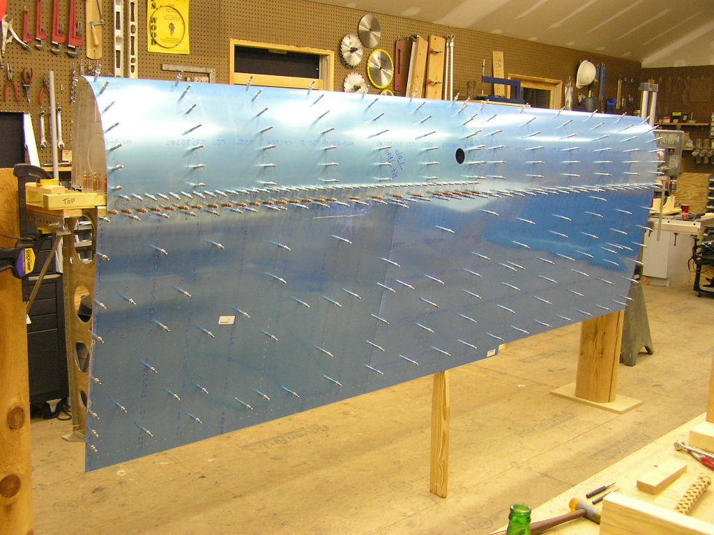
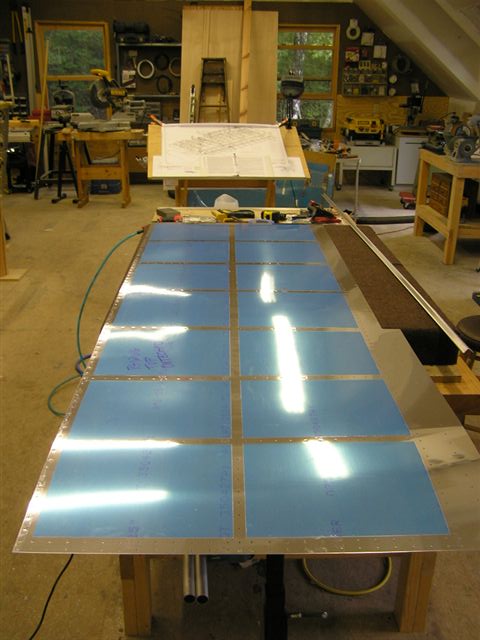
in the top and bottom skin. I then clecoed the top skins to the wing. Fellow EAAer Jim Olson came by and helped me rivet the top
skin. We then took the wing off the stand and placed it in
the new wing cradle. Thanks Jim.
|
9.0 |
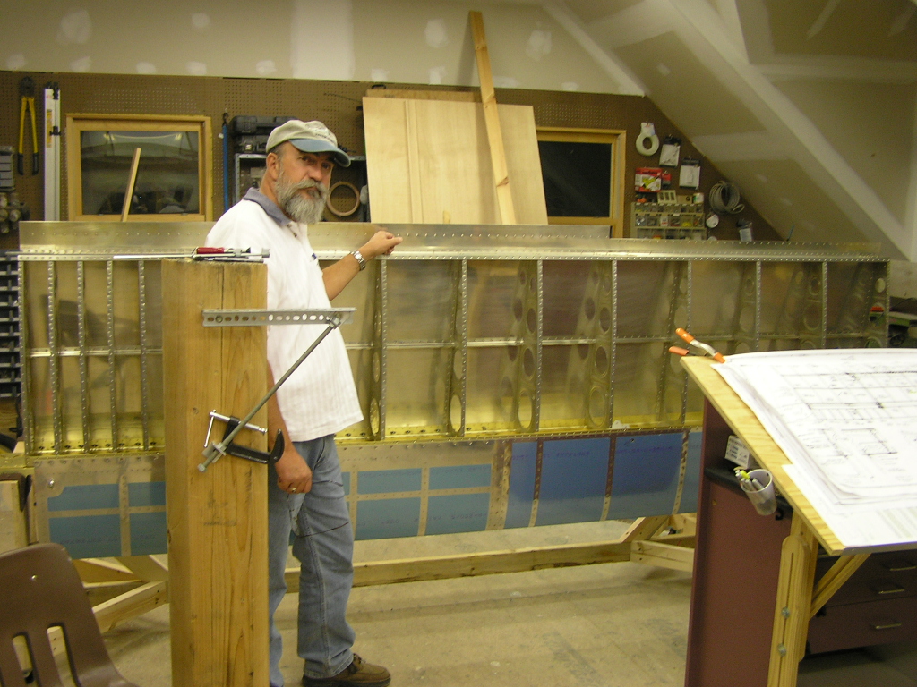
| 10/17/06 | Another EAA friend, Anton D'Allen came over
tonight and helped me rivet the top skin the the rear spar.
I also began working on the aileron attach brackets. I
deburred the brackets and clecoed the assembled brackets to the
rear spar.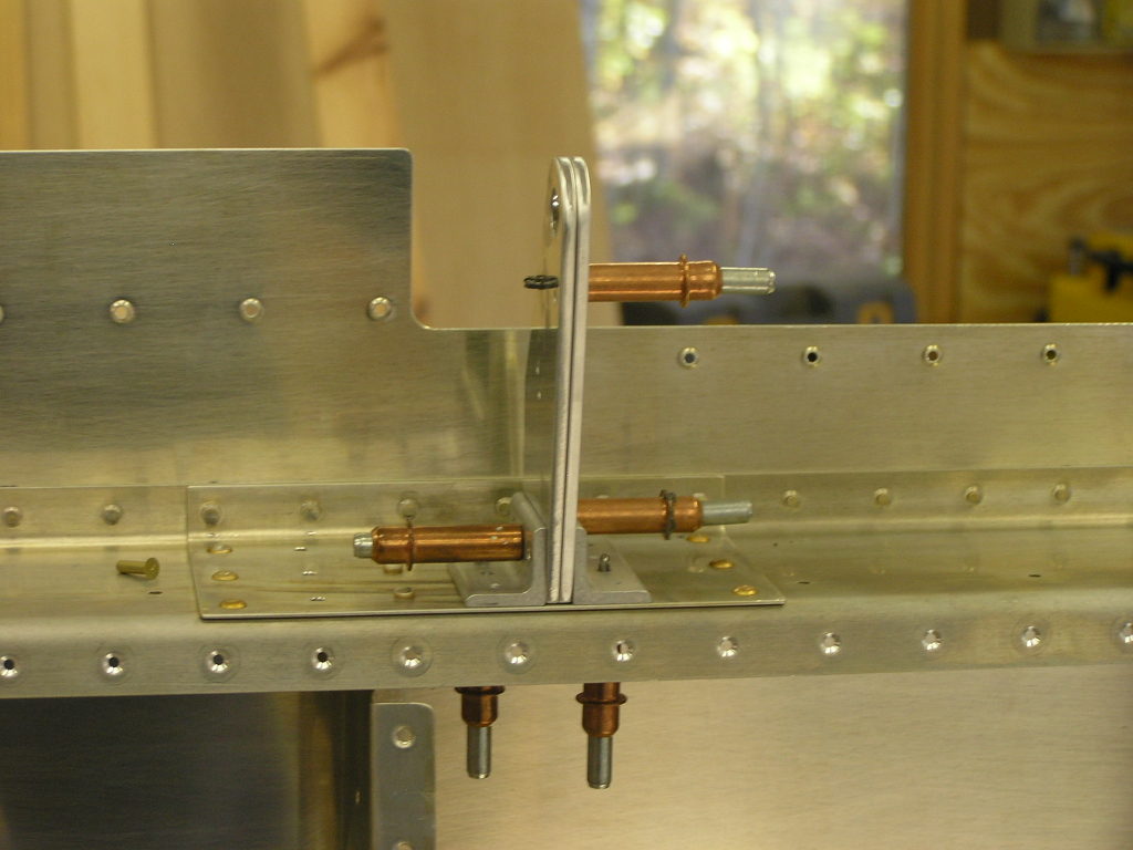 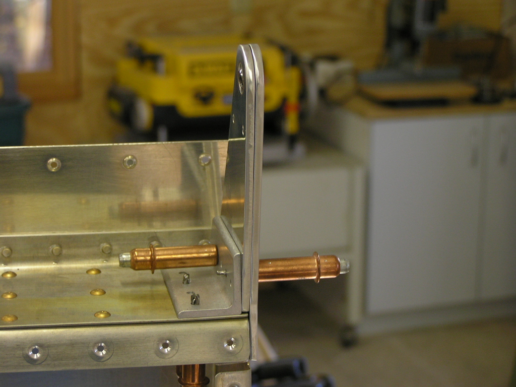
I applied torque seal to the bolts attaching the fuel tank and
the bellcrank brackets. |
2.0 |
| 10/18/06 | Today I received my Bob Archer wingtip antennas. I am planning on putting the NAV antenna in the top of the right wingtip, the Marker Beacon antenna in the bottom of the right wingtip and the #2 COM antenna in the left wingtip. | |
|
Total Hours |
50.0 | |
| Next: Wings 2 |