
Home
Shop
Tools
Empennage
Wings
Fuselage
Fuselage 2
Fuselage 3
Fuselage 4
Fuselage 5
Wing/Fuselage Fitting
Setting Wing
Incidence
Forward
Attach Brackets
Flap
Assembly
Wing Root Fairings
Installing
Control System
Fitting the Empennage
Fitting the HS
Installing the Pushrod
Drilling Elevator Horns
Fitting the VS
Fitting the Rudder
Brake & Fuel Lines
Installing the Front Deck
Removed Wings
Installing Cabin Brake Lines
Fuselage 6
Panel
Firewall Forward
Canopy
Wiring
Miscellaneous
Fuselage 5
|
Date |
Description of Task | Hours |
| 11/6/07 | Today I ordered the
Finish Kit! It should ship sometime around the
second week of January. |
|
| 11/9/07 | Tonight Lynne helped me out by helping cut out
the firewall insulation I purchased from
Abby at Flightline Interiors.
She made a pattern using newspaper and we then transferred the
pattern to the .025 insulating blanket and cut out with a razor
knife.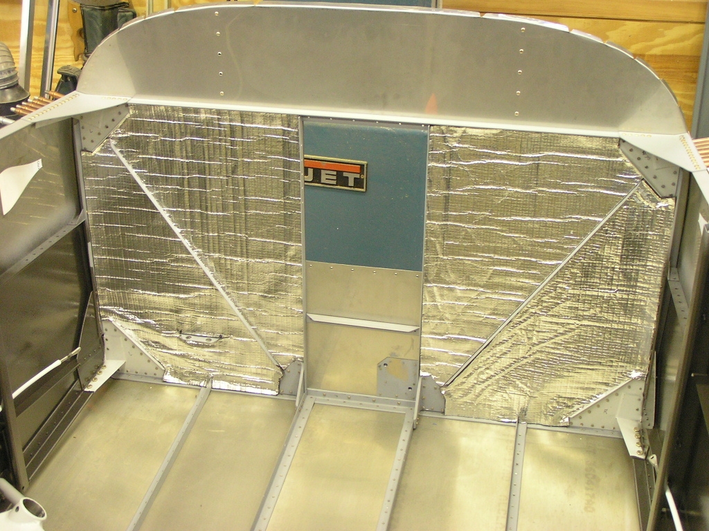 Before I install all the plumbing for the fuel and vent lines I wanted
to paint the interior. I taped off the forward cabin area
and primed and painted the areas that will be seen after the
upholstery is installed. I have Jim Olsen and
Dan Miller coming over on Saturday
to help install the wings so I made final preparations. |
3.0 |
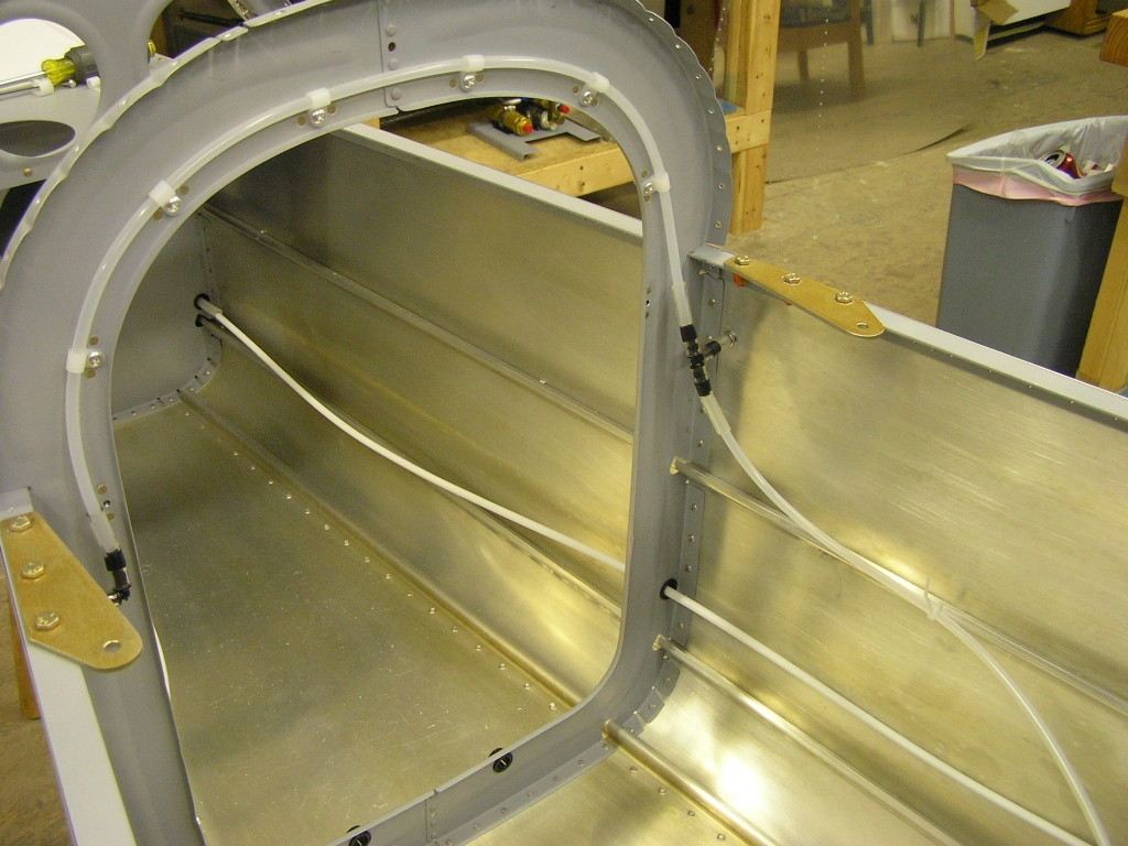
| 11/10/07 | Before the crew arrived I cut the fuel line
stubs through the firewall back to 2.50". I shoved as much
of the line as possible back inside the fuselage before cutting.
I installed the nut and sleeve and then flared both stubs.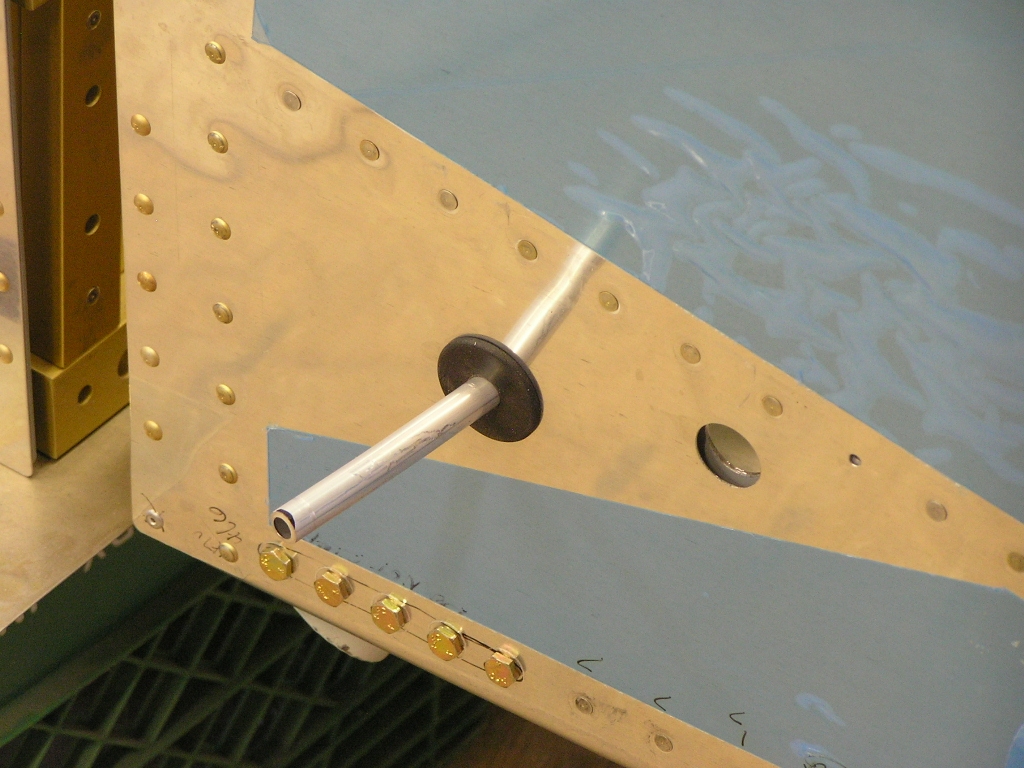 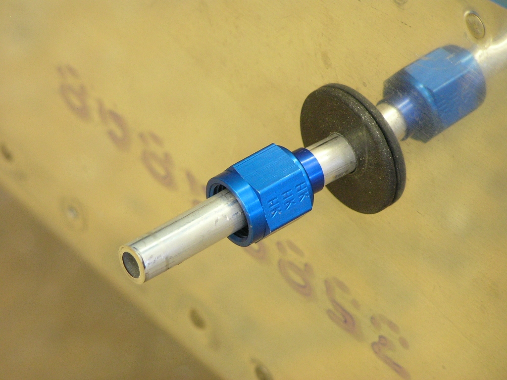 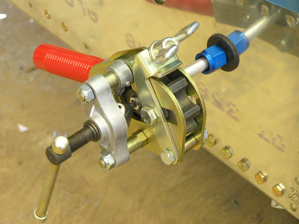 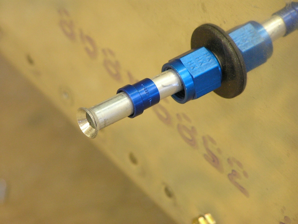 I worked on the rudder cable covers where they exit the aft fuselage.
I dimpled and primed the covers and dimpled the holes in the
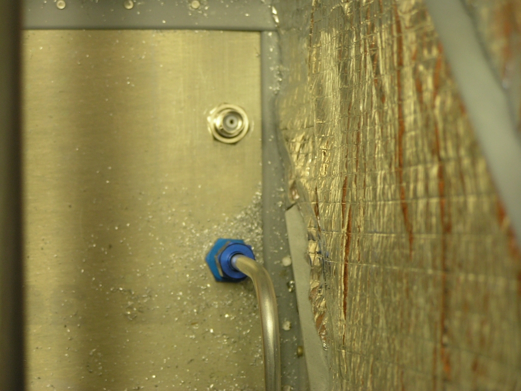
fuselage. Next, I installed the static line at the F707 bulkhead.
I installed platenuts and secured the static line with .025
plastic clamps. Jim and Dan arrived at 5:00 and with Lynne
inside the fuselage for ballast we installed the wings.
The wings fit tightly but everything lined up perfectly and the
hardware store bolts went in with only minor persuasion. |
5.0 |
| Setting Wing Incidence | ||
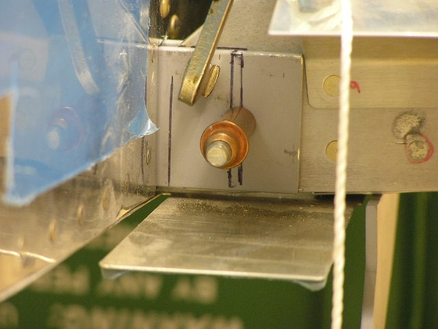
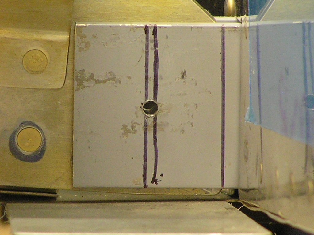
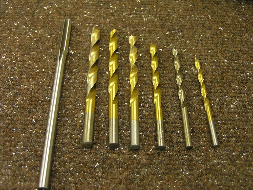
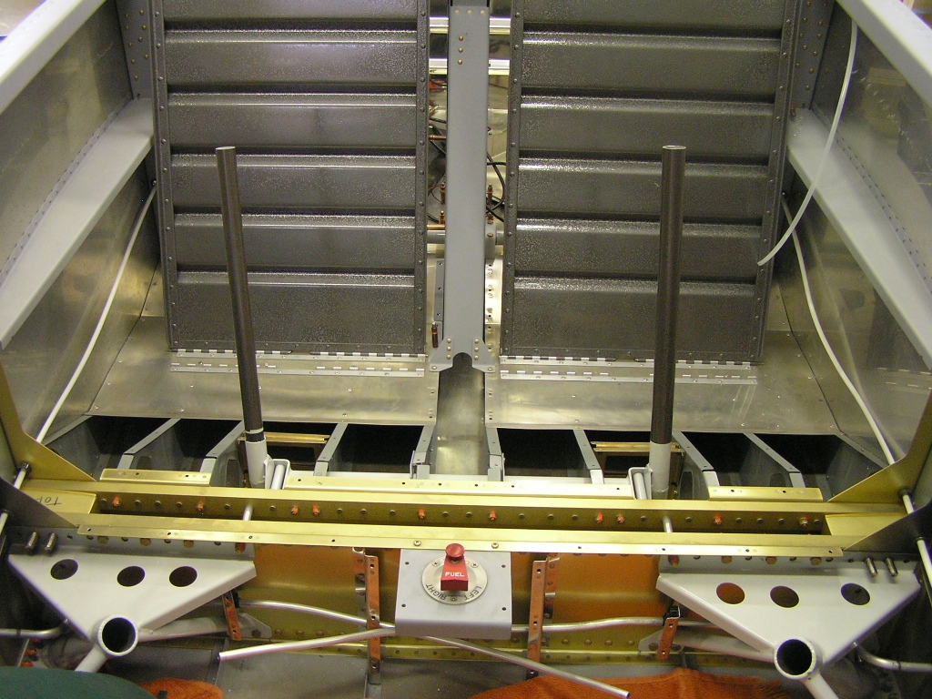
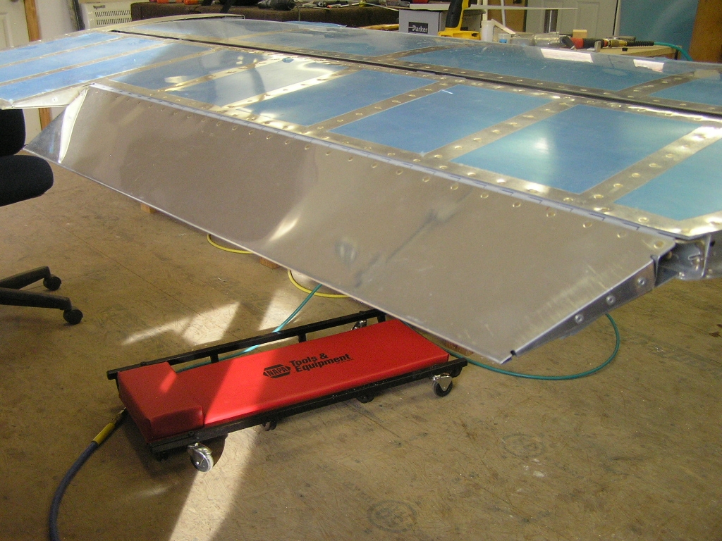
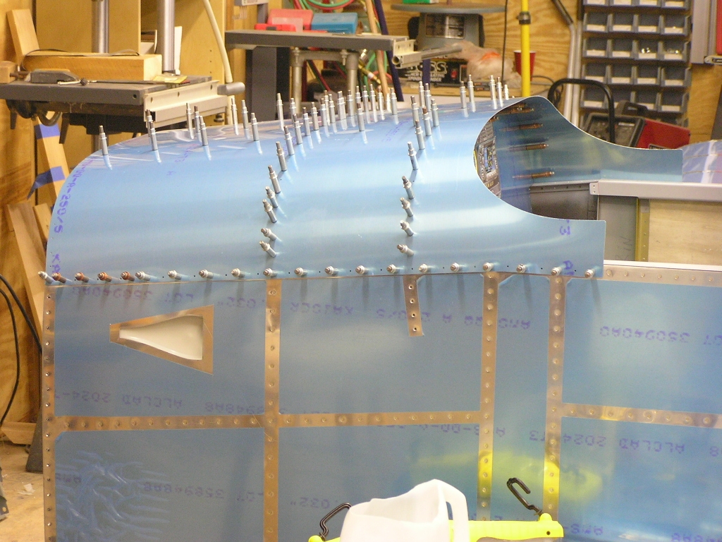
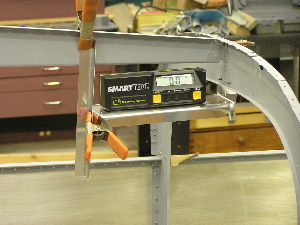
| 11/11/07 | Today I can say I drilled
the rear spars! I can also say that I spent 7 hours
doing it. I began by leveling the plane laterally along
the center section spar carry through and longitudinally along
the longerons using my digital level. Next I measured the
forward sweep by hanging four plumb bobs off the leading edge
and pulling a string to adjust until straight. This is a
task that required Lynne's help to hold the tail steady so I
could manipulate the wing fore and aft. My plane had a
small forward sweep (5/16") but was able to reduce this down to
1/16" (Van's says within 1/2" is fine). After clamping the rear spar I measured from each wingtip to
the tailcone and was surprised to find that both wings were
EXACTLY the same. Next, in order to set the incidence I
had to cut a block of wood 4 5/64" and attach it to my 4' level.
I measured at the third inboard rib as well as at the mid-wing
on both wings. The incidence was nearly perfect but I
adjusted each wing until it was absolutely perfect and clamped
again. At each step I would re-check the plane for level, re-check the sweep, re-check the triangulation and re-check the incidence. Finally, it was as ready as it will ever be...time to drill. I cut a piece of 2x4 into a block 1 1/2" x 2" and drilled a 1/8" hole on the drill press. This block was used as a drill guide to ensure a perfectly perpendicular hole through the rear spar. Next, before drilling, I measured 5/8" from all sides and
marked the rear spar. All I need to do now is make sure to
drill within the lines. I used a punch to mark dead-center
and, with the block clamped to the rear spar, Drilled the hole.
I then repeated on the left wing spar and clecoed and clamped. Next, I re-checked all the measurements and was relieved to
find everything still holding true. I will be enlarging
the holes incrementally until I get it to within one step of the
final diameter of 5/16" where I will use a reamer to true the
hole. |
7.0 |
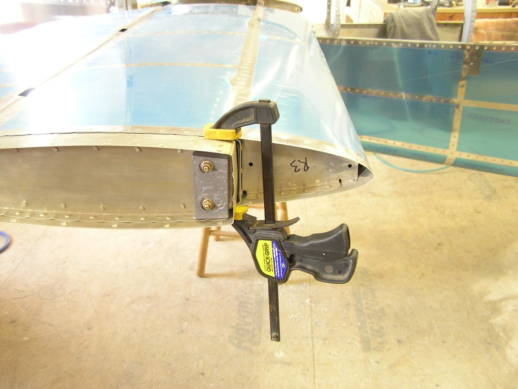
| 11/12/07 | Drilled the rear spar to 5/16" and bolted.
I began installing the left aileron.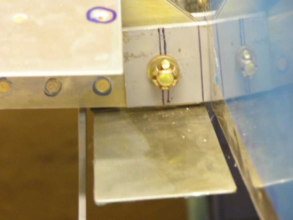 |
2.0 |
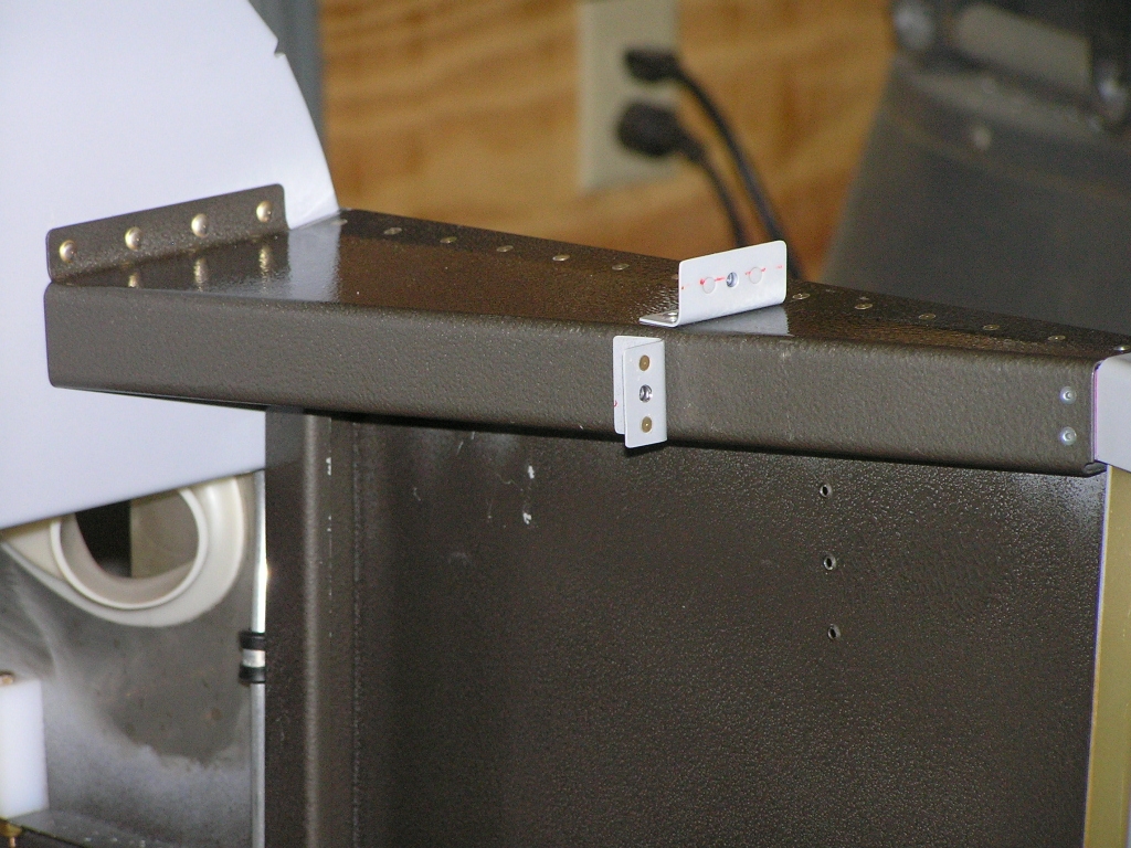
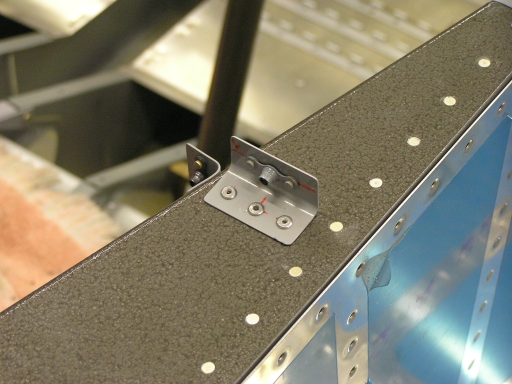
| 11/13/07 | Finished installing the left aileron.
Attached the aileron alignment angle to set the aileron
position. I also clamped the horizontal stabilizer to the
aft deck. I am using a piece of 3/4" delrin rod as an
aileron stop. What baffles me is what other builders do
with the screw where it hits the aileron top skin... 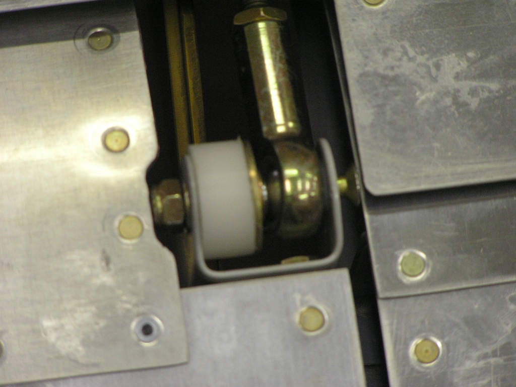 |
1.5 |
| 11/14/07 | Installed the right aileron as well as the
flaps. I sanded the control "sticks" and painted with the
rattle can.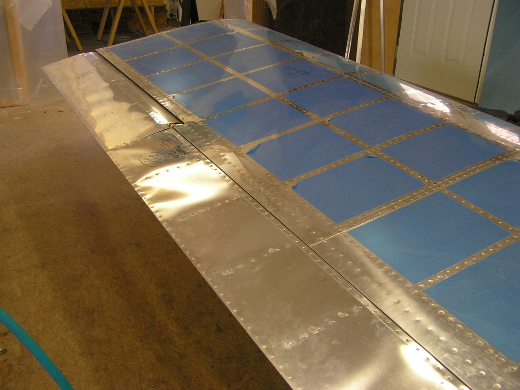 |
1.5 |
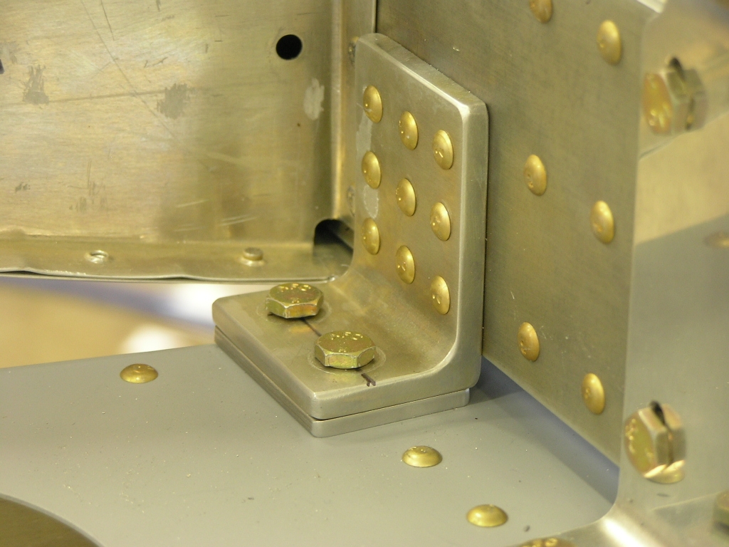
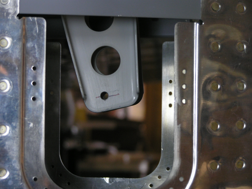
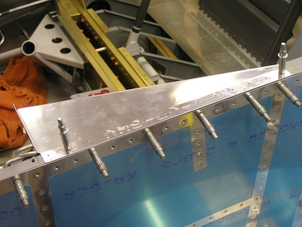
| Forward Attach Brackets | ||
| 11/16/07 | I took the day off from real work today so I
could seriously work on the plane. Lynne is out of town as
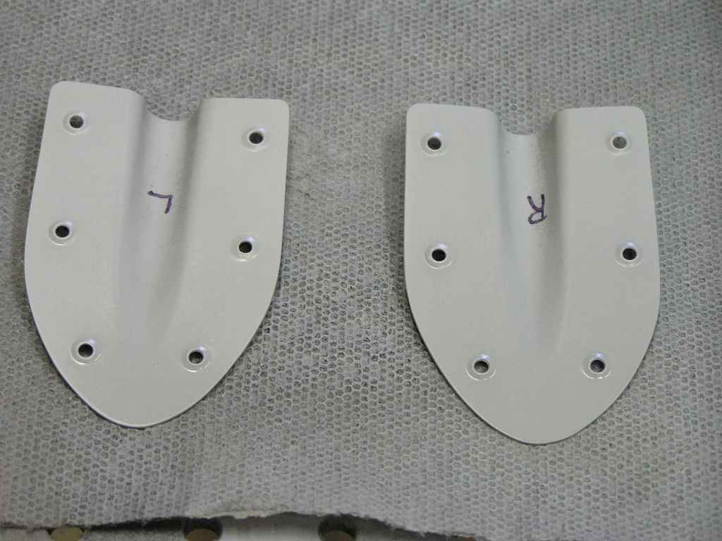
well so I had no distractions. I fabricated the forward
attach brackets and bent, clamped and drilled them to the
fuselage. I drilled the .025" hole through the T-905.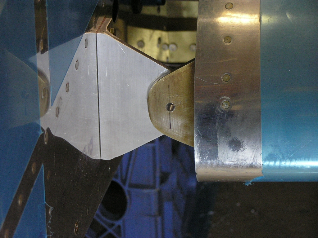 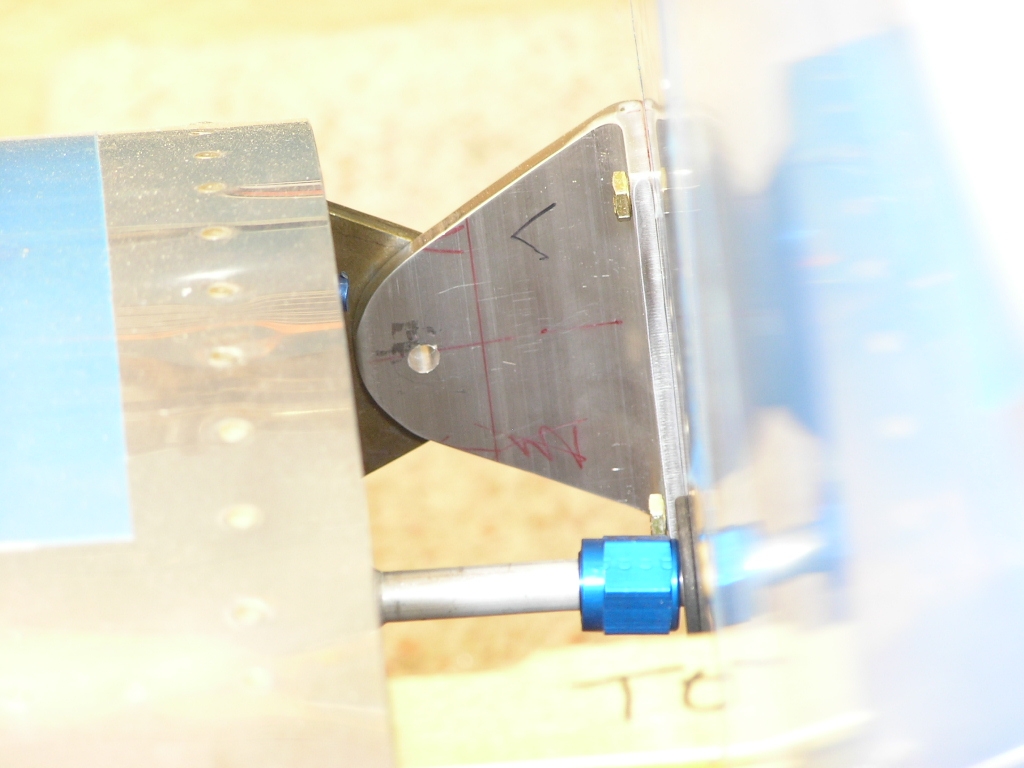 Flap Assembly Wing Root Fairings
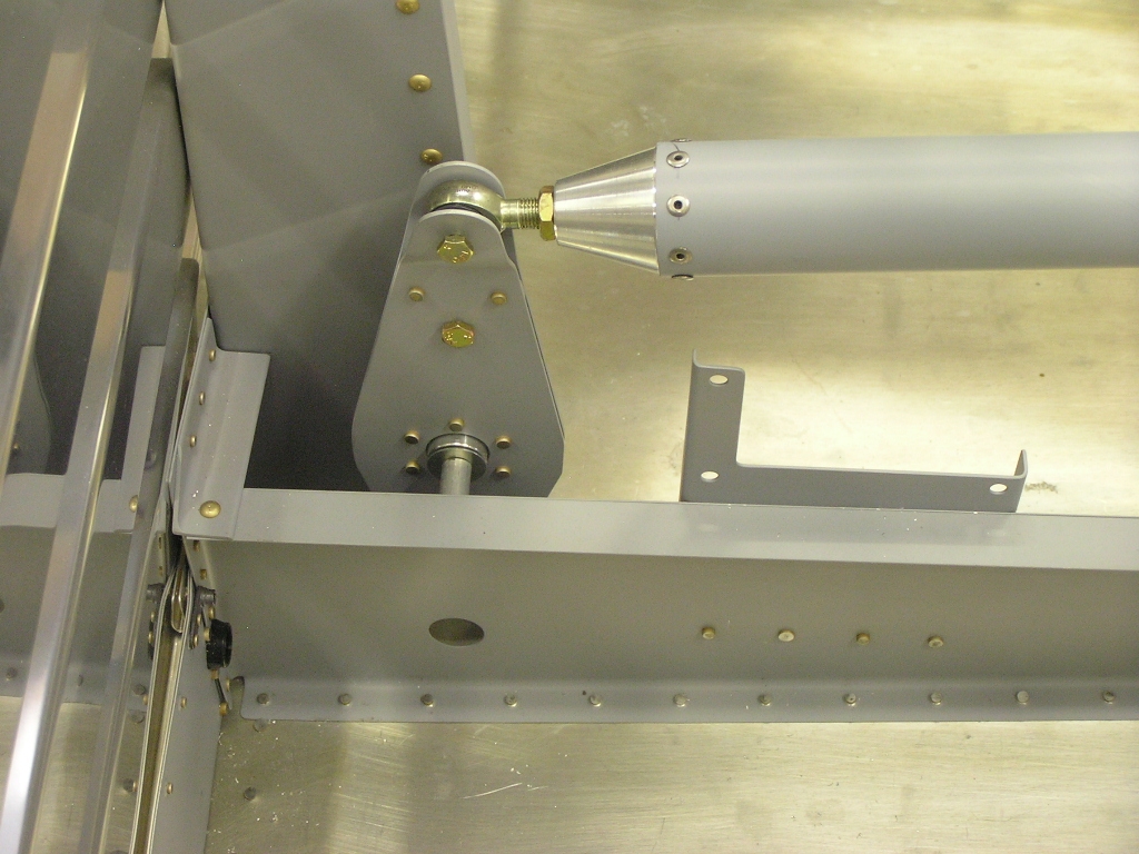
Installing the Control
System I am not attempting to get the rigging perfect now since this
will all be disassembled. The purpose is to get it roughly
rigged and adjusted so when I reassemble at the airport I will
only need to "tweak" it for it to be rigged for first flight.
Fitting the Empennage
Fitting the Horizontal Stabilizer
Installing the Pushrod and
Setting the Elevator Travel Stops
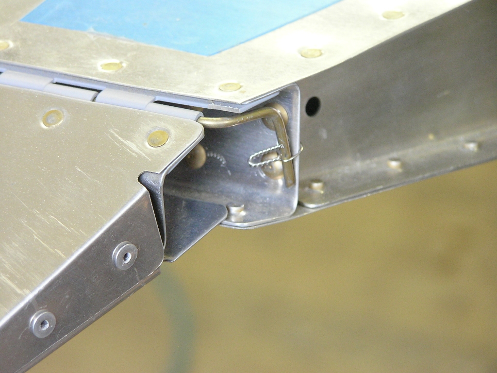
While I was at it, I bent the trim tab hinge pin and safety
wired. |
10.0 |
| 11/17/07 | I primed the exterior of the F-790 elevator
pushrod as well as the small tube. I measured out the
circumference of the fat tube and divided into eight segments.
I wrapped the paper around the tube and marked the location for
the eight rivets. I inserted the rod ends and drilled to
#30. Finally, I installed the MSP-42 pulled rivets.
Drilling the Elevator Horns
I installed the rod end bearings into the F-790 pushrod and
mounted to the bellcrank and the elevator horns. I
adjusted until the bellcrank was vertical.
Fitting the Vertical
Stabilizer
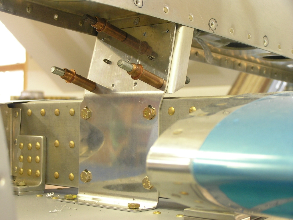
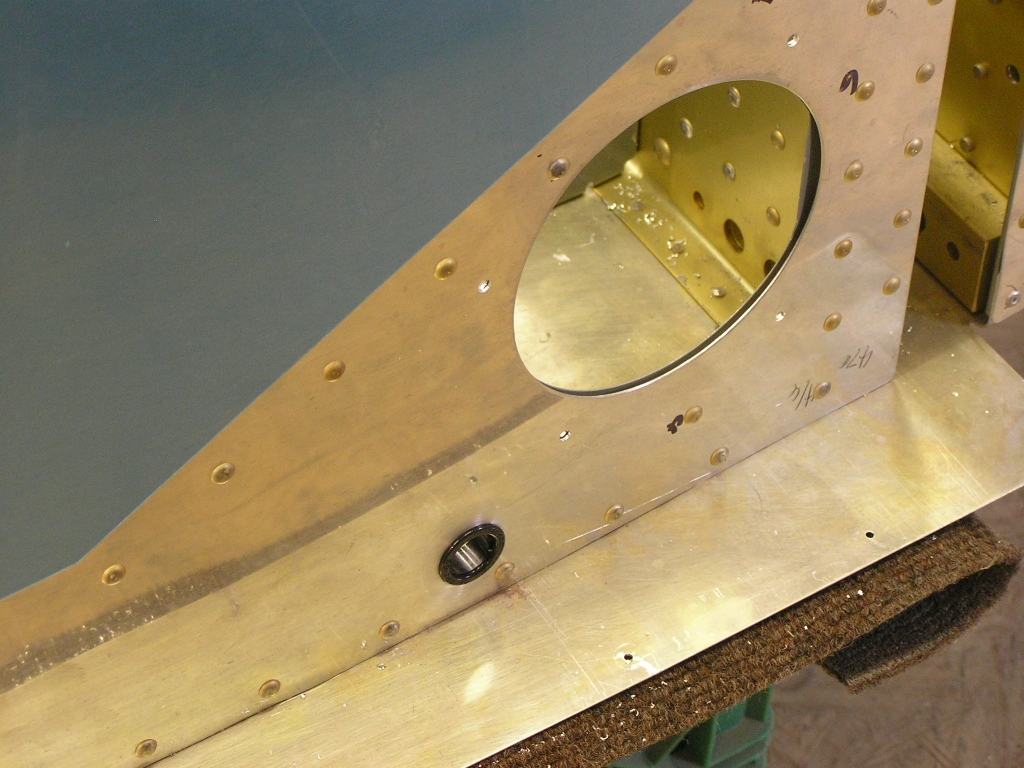
Next, I drilled the rear spar to the F-712 bulkhead. Then
you have to back-drill the four holes in the tie-down bracket
through the rear spar. (In order to do this you must first
remove the elevators in order to have room to get an angle drill
inside the fuselage). Finally, I drilled the holes to full
size and bolted the rear spar to the bulkhead. Fitting the
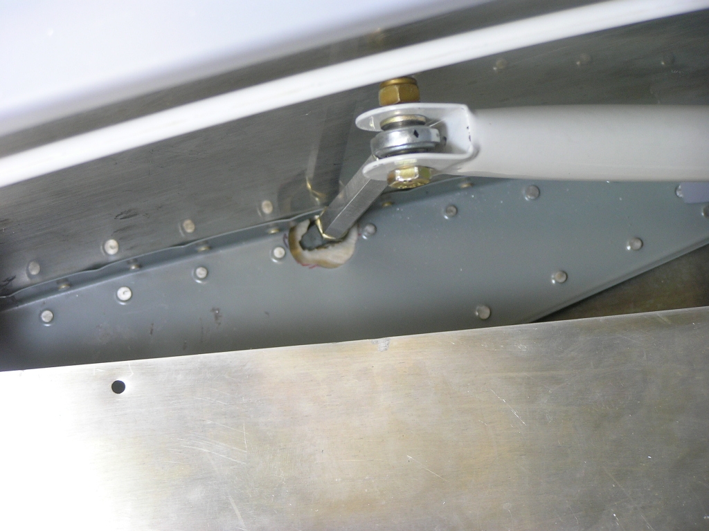
Rudder
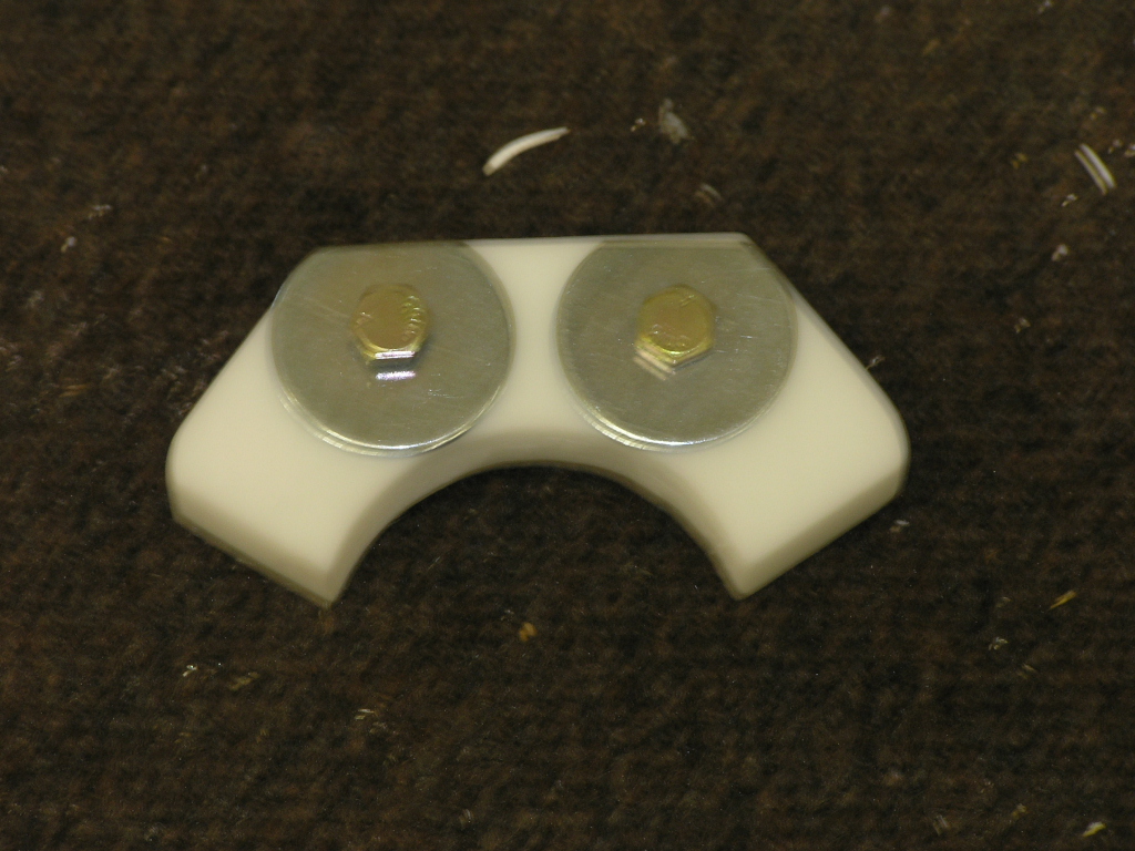
It mounts to the bottom of the lower hinge bracket of the
vertical stabilizer and alleviates the need for the ugly rudder
stops riveted to the exterior of the fuselage. |
8.0 |
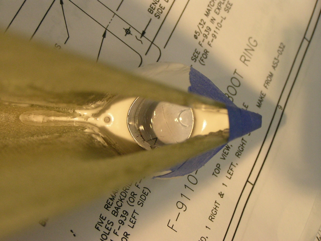
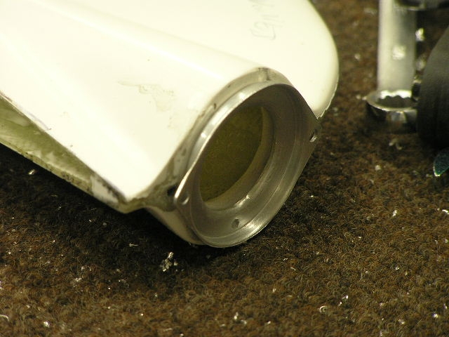
| 11/18/07 | Once the rudder was installed, it was apparent
I needed to do more trimming on the lower fiberglass fairing.
I took my time and trimmed very carefully until I had a nice
fit. I also drilled the rear light hole to 1.0" for the
Whelen light. I also purchased the LED replacement light
from
Eric Jones at Perihelion
Designs. 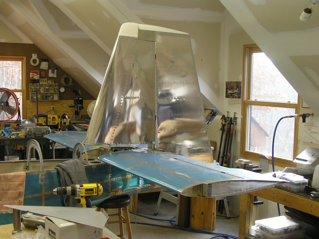 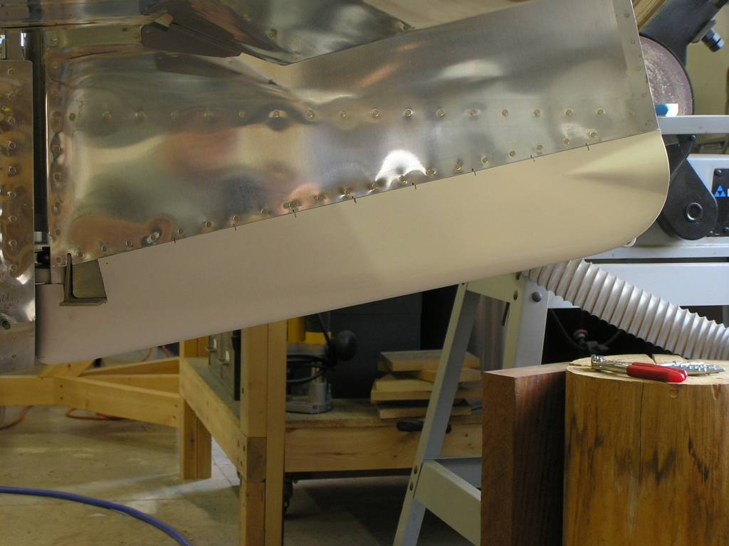 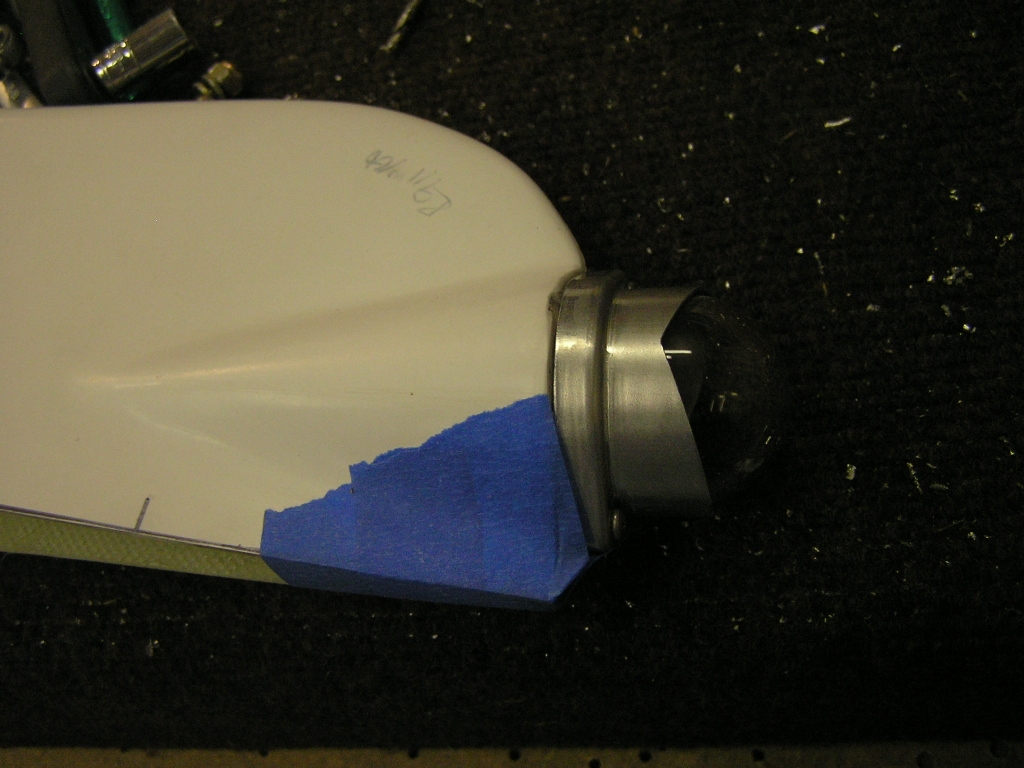
I then mixed up some epoxy and made a thick slurry with micro
balloons and filled the area around the screws. After it
dries I will have a built-in nut for the screws.
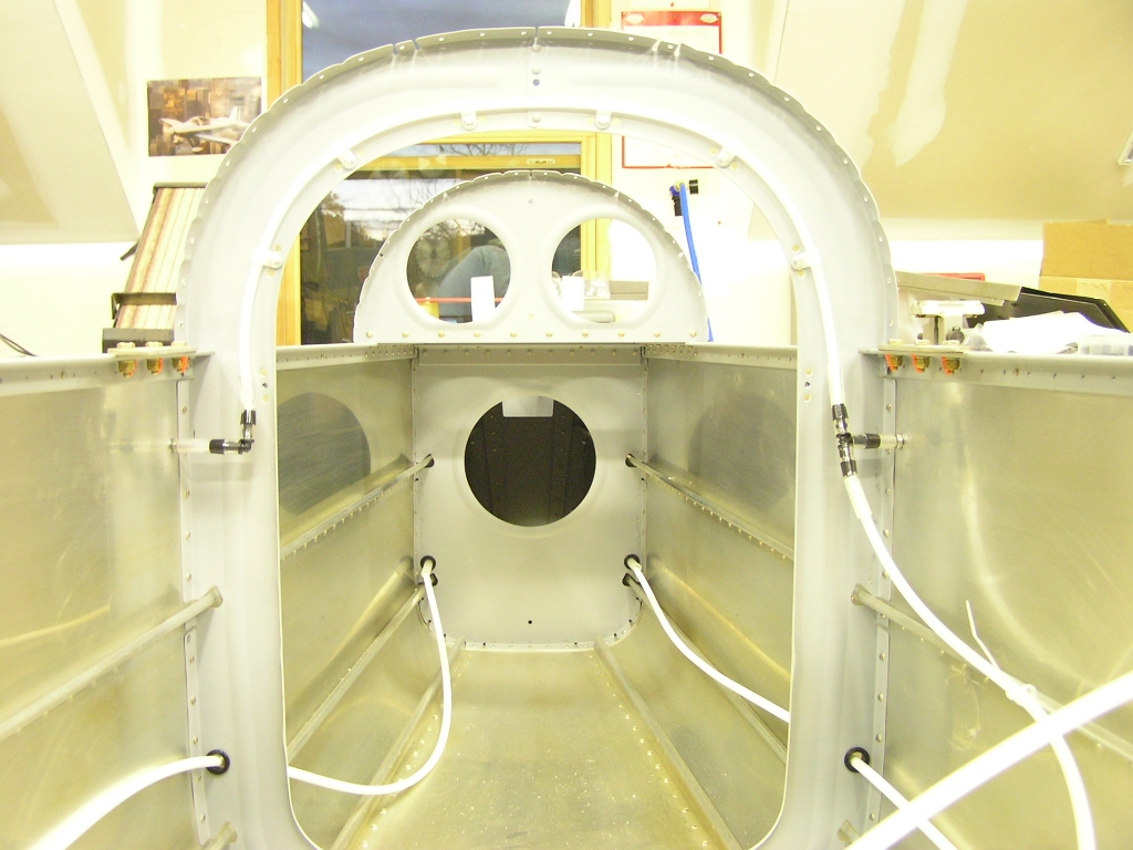
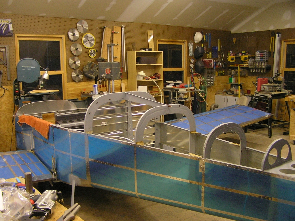
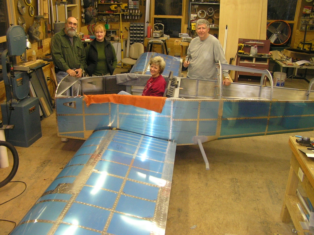
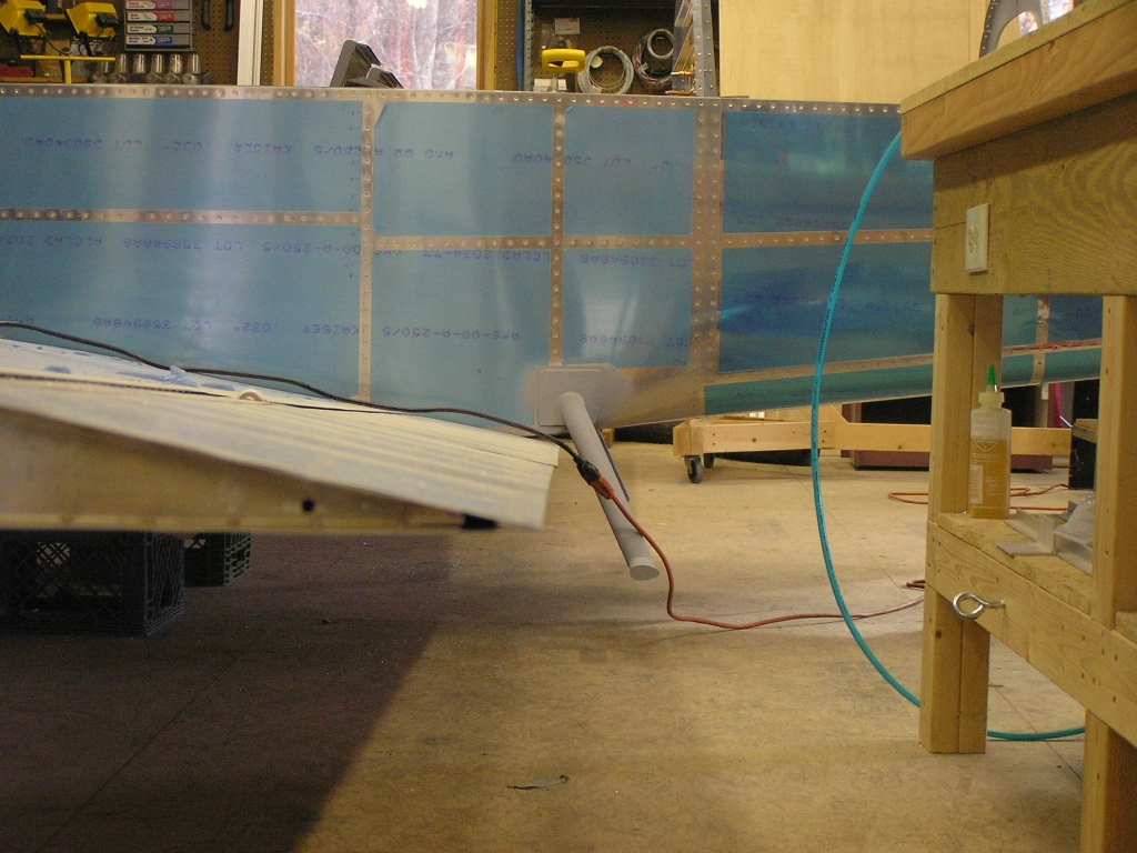
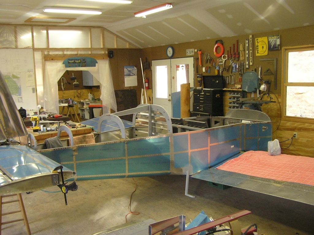
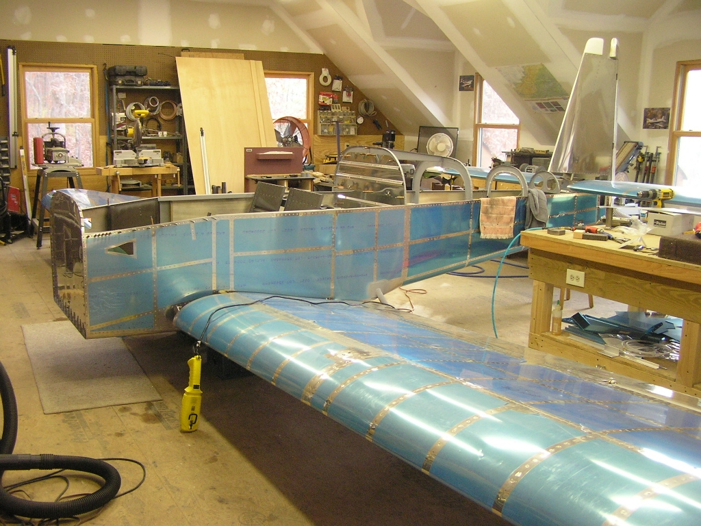
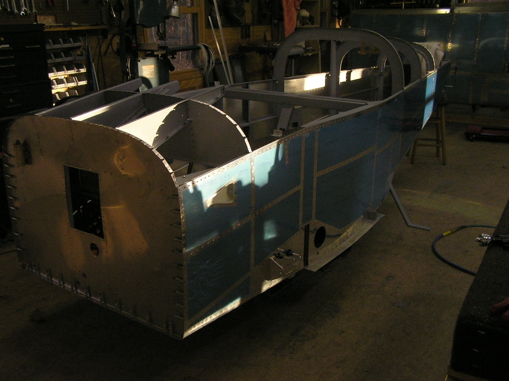
Well, here we have a "mostly" assembled airplane. |
2.0 |
| Finishing the Forward Fuselage | ||
| Installing Brake & Fuel Lines | ||
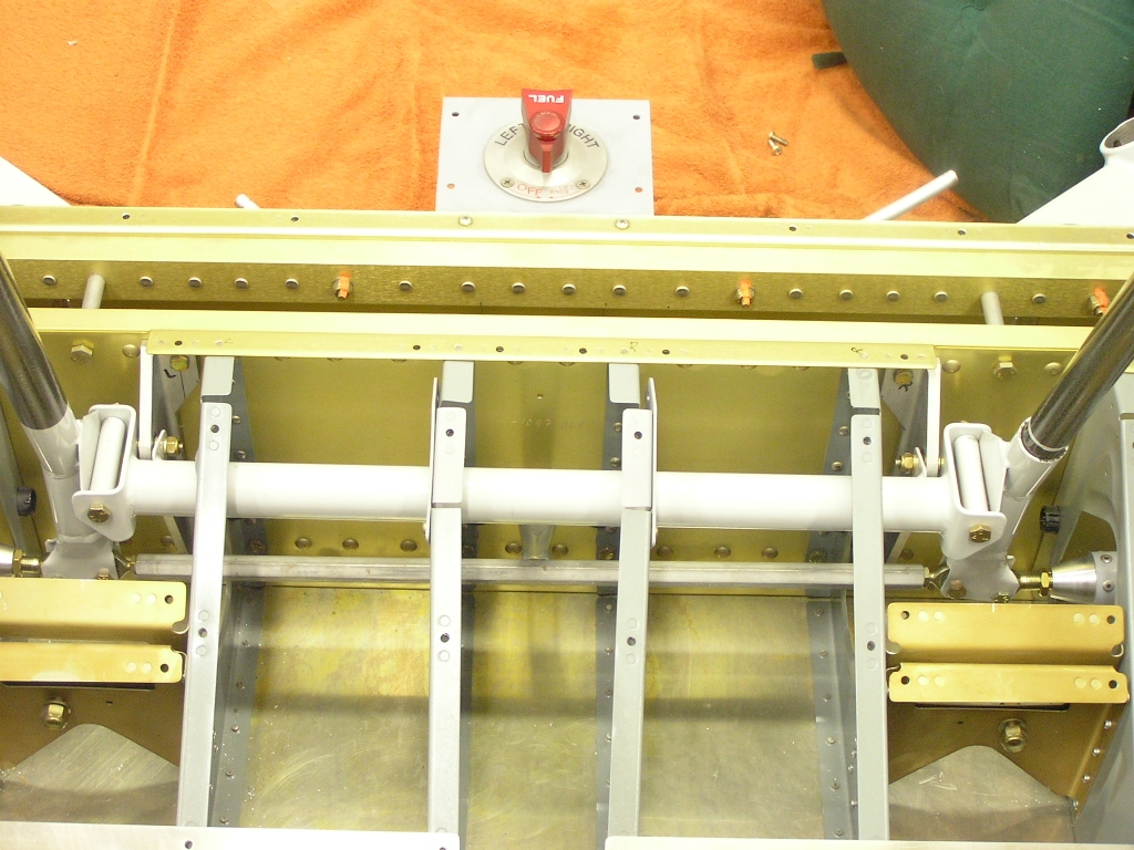
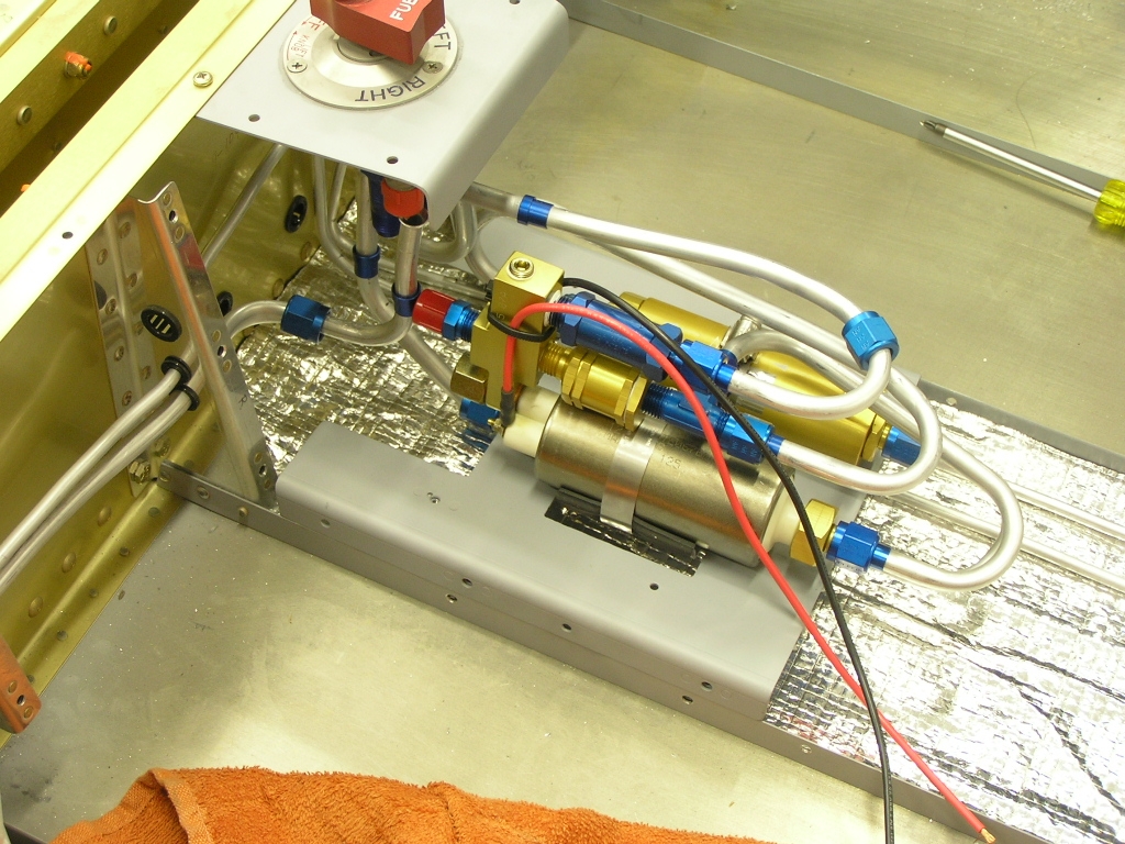
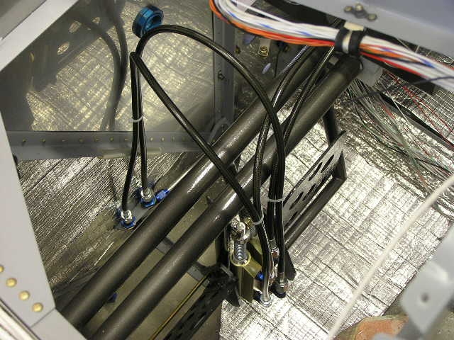
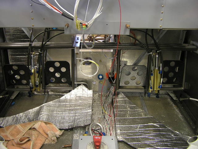
| 11/25/07 | Finally got the Thanksgiving guests to leave
and worked on plumbing the brake lines as well as the
Airflow Performance fuel
pump/filter kit. I cut a piece of the soundproofing
insulation for the tunnel and will let the fuel and brake lines
lay on this for padding.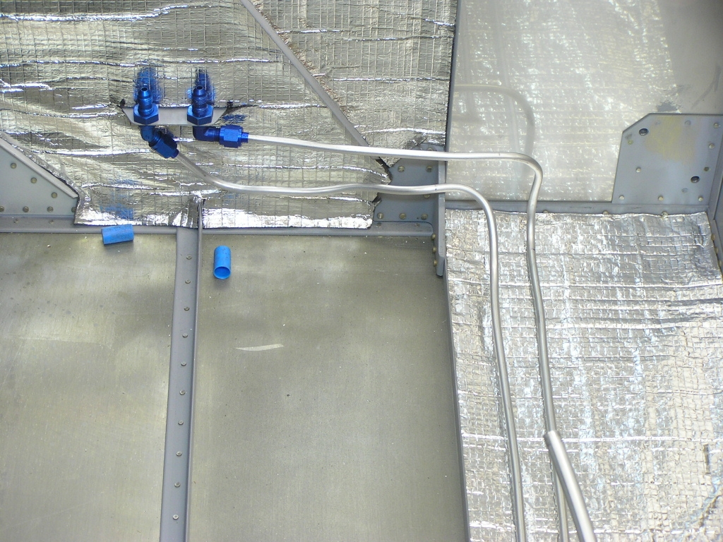  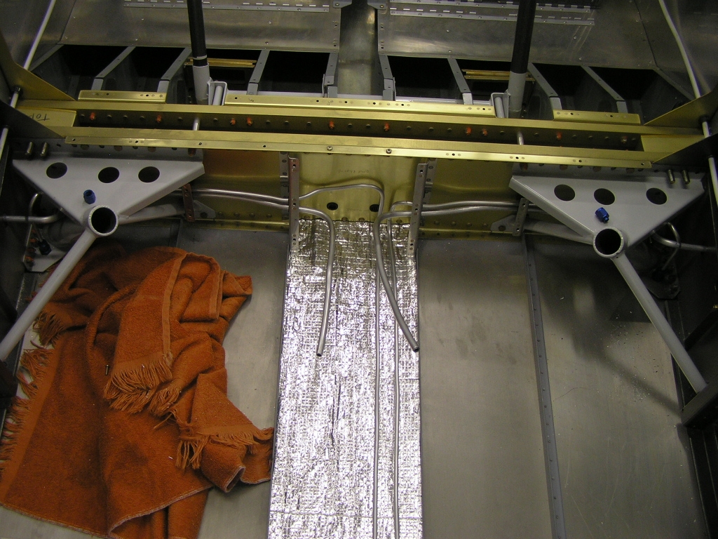
Next, I bent and flared the fuel lines where they will attach to
the Andair fuel valve. I then worked on bending and installing the various tubing
for the fuel pump. I got stumped when I found out that the
fuel pump outlet interferes with the right tank inlet on the
valve. |
3.0 |
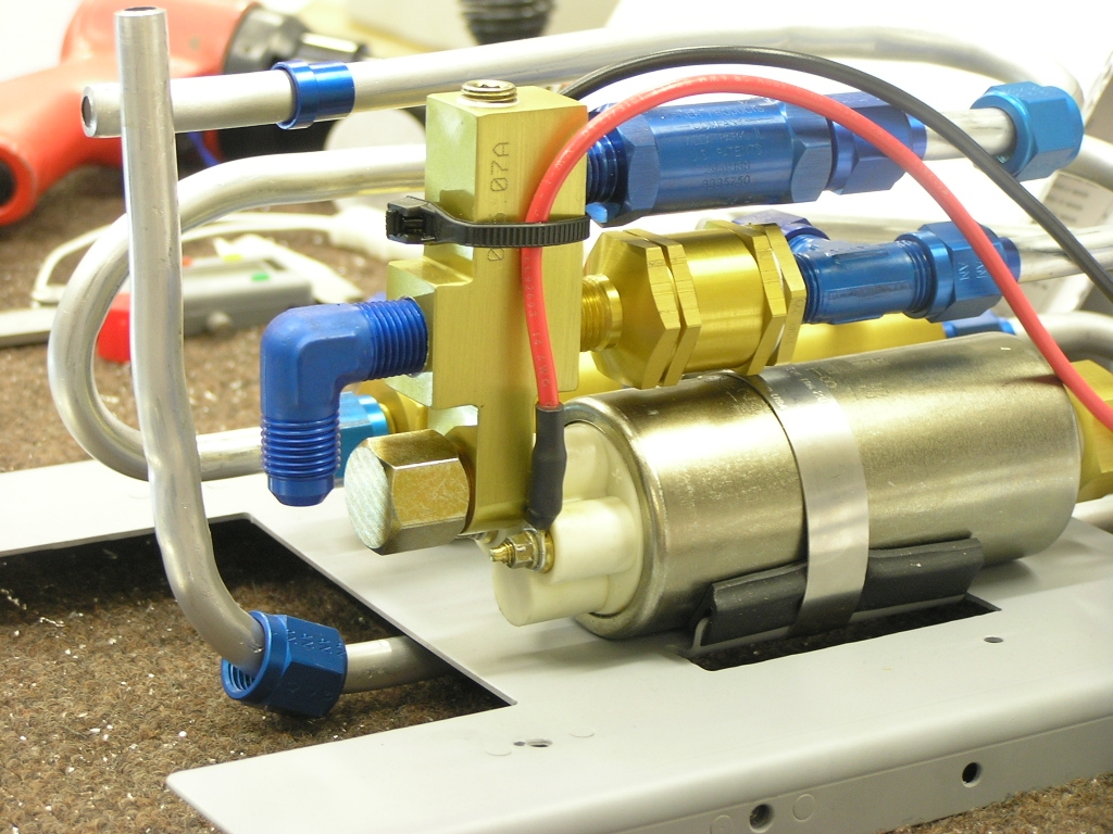
| 11/26/07 | I spoke with Don Rivera
at AFP today and he felt the 90 degree fitting was a great
solution and would not affect the performance of the IO-360.
I installed the fitting with a dab of EZ-Turn and measured, cut
and flared the tube and installed.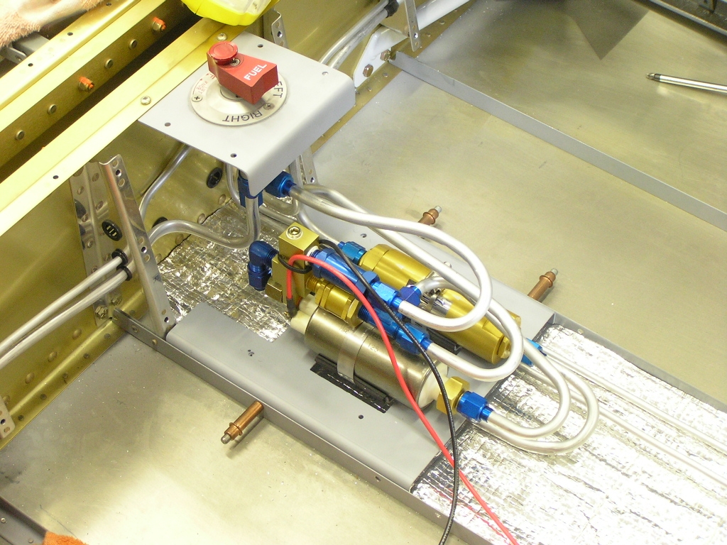 |
1.0 |
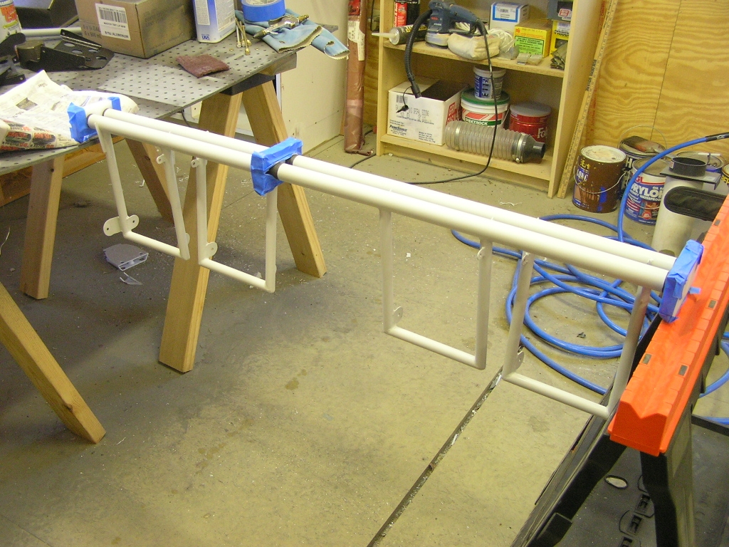
| 11/30/07 | Tonight I bent and test fit the left vent
tubing. I also ground down the threads on the AN832-4D
unions and cut the tips 45°.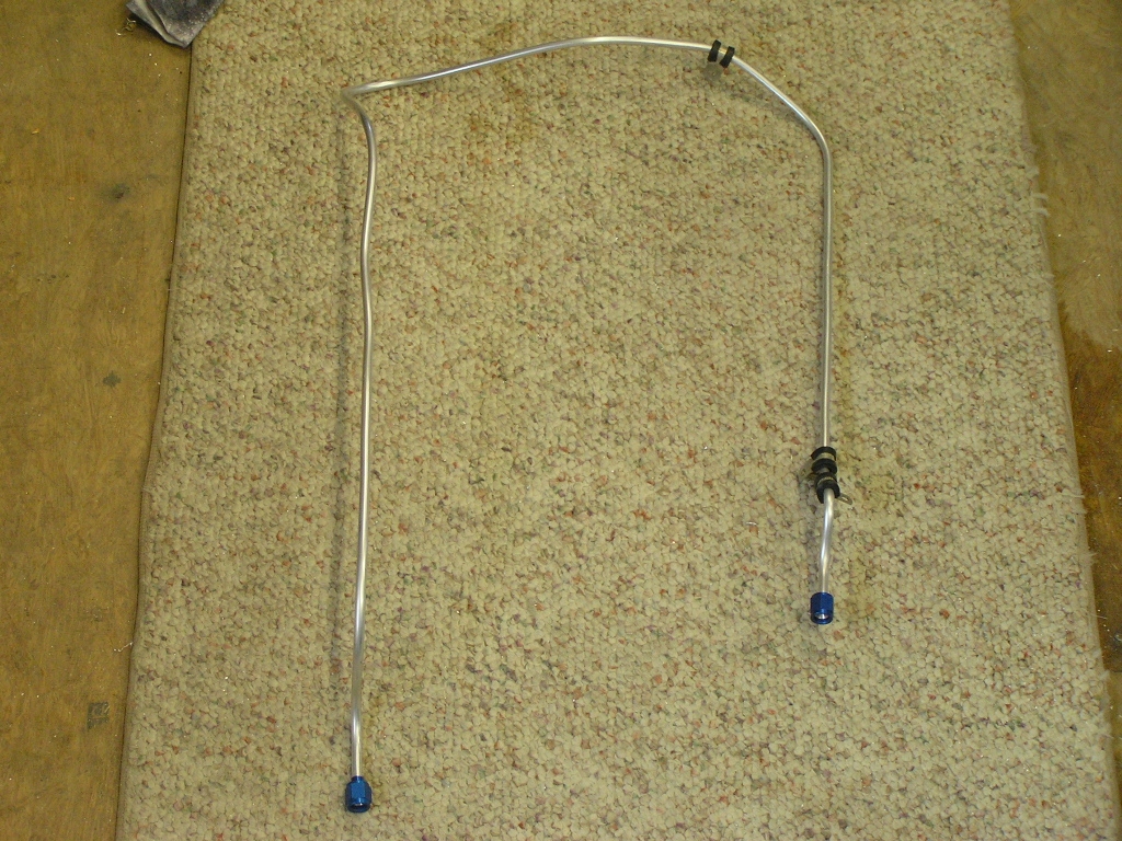 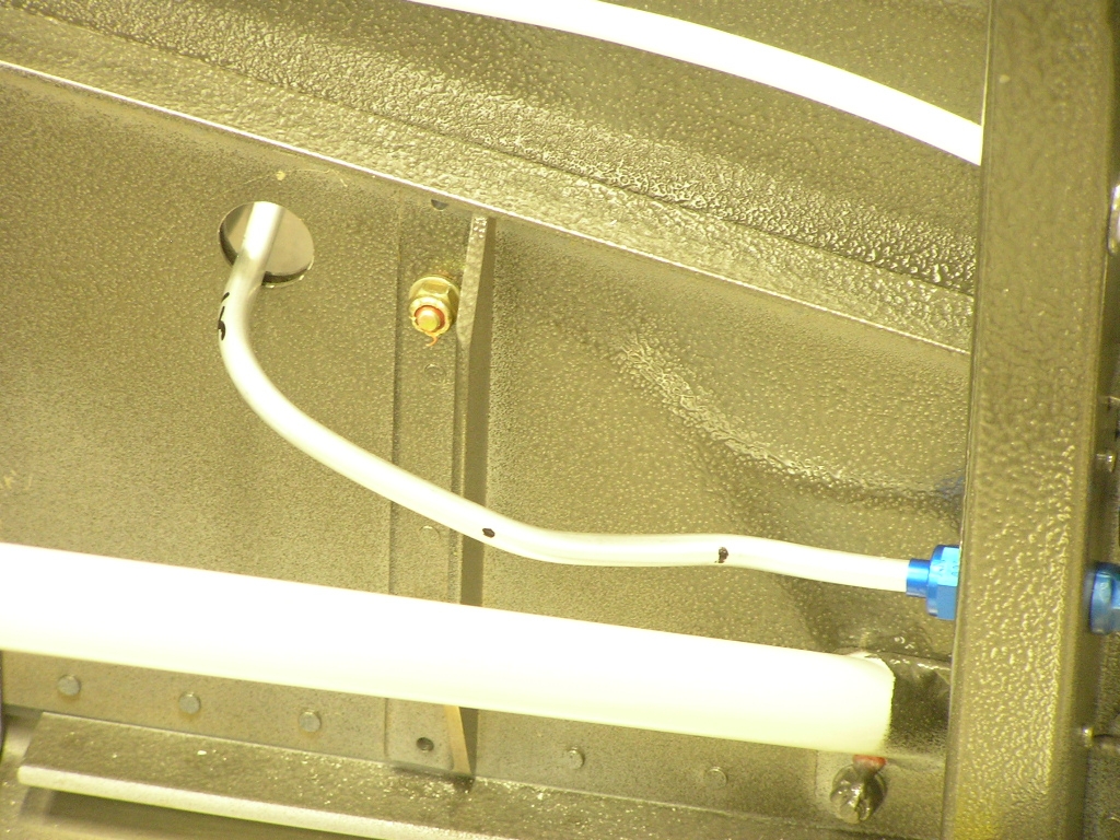 |
2.0 |
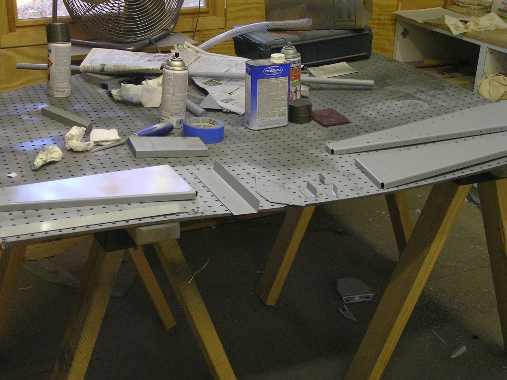
| 12/1/07 | Bent and test fitted the right side vent
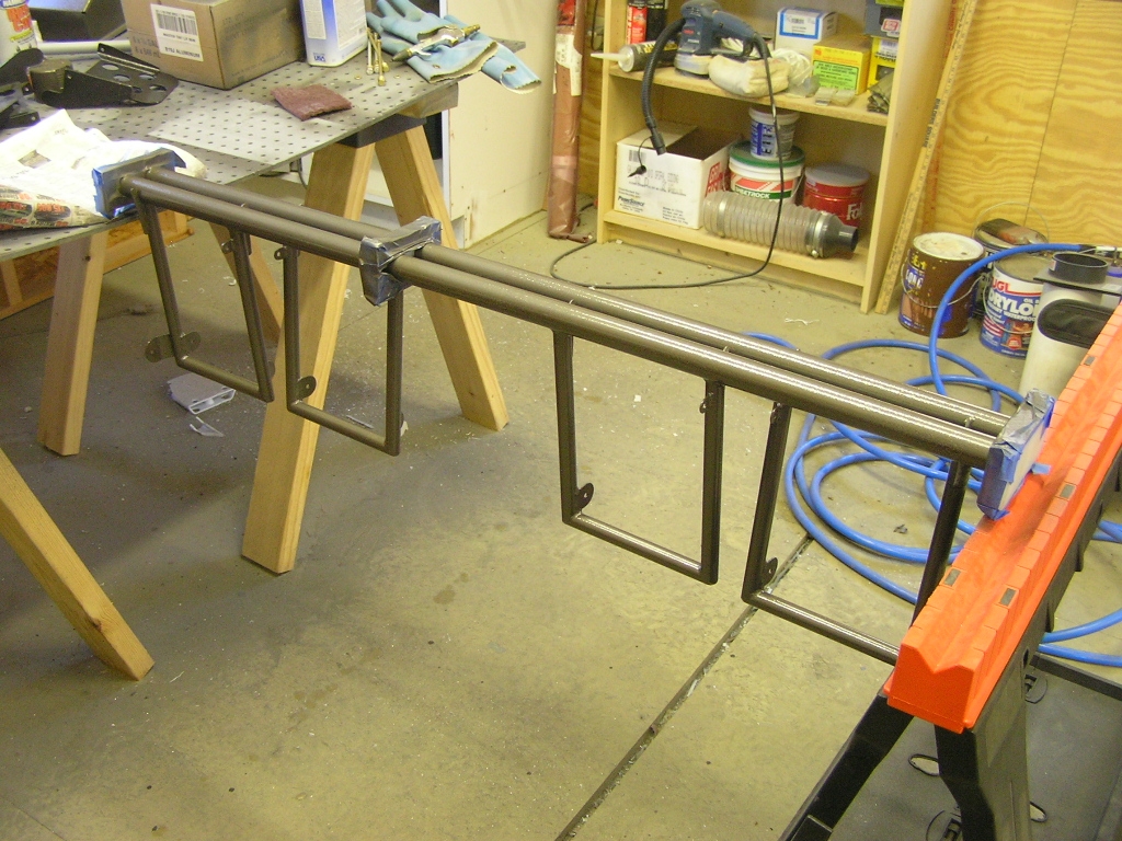
tubing.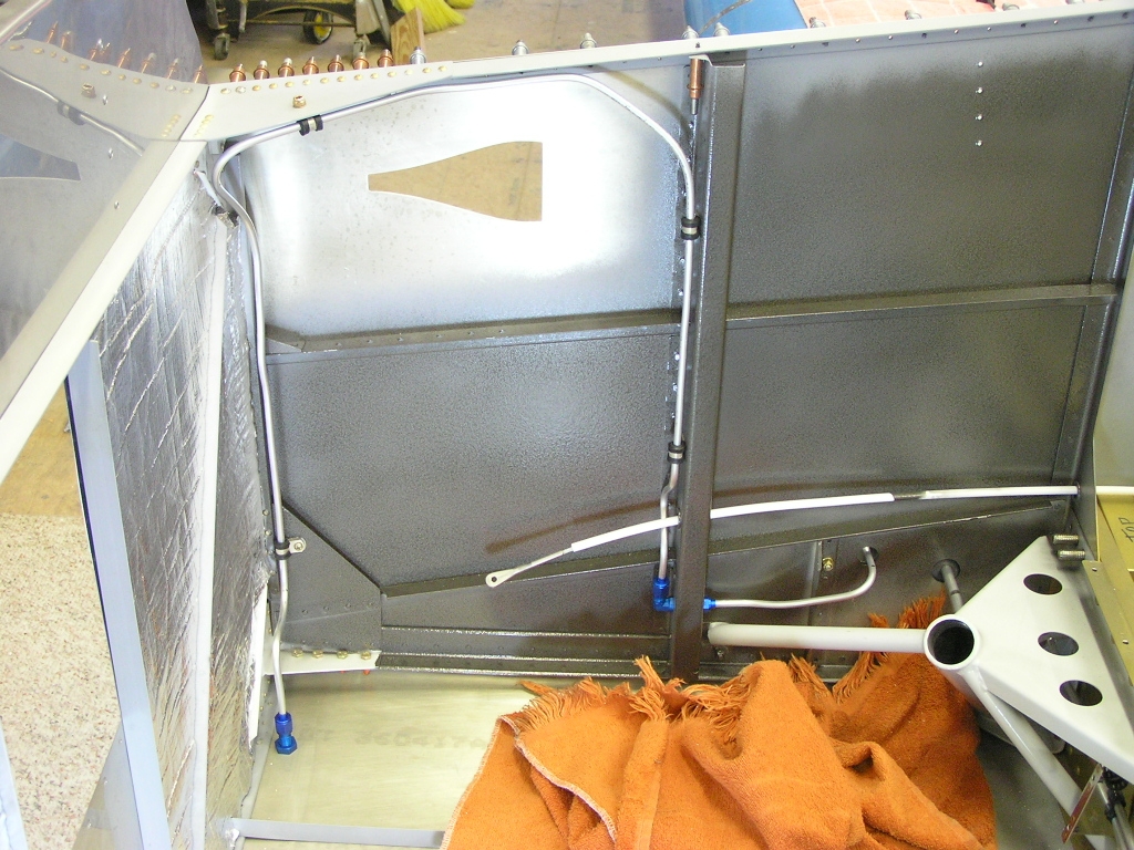 I don't like the light gray powder-coated color of the rudder pedals so
I removed the brake pedals and the master cylinders. I
then scuffed the powder coating and painted with the hammered
gray rattle can.
Installing the Front Deck |
3.0 |
| 12/4/07 | Installed the brake pedals onto the rudder
assembly and installed in the fuselage. (I installed the
assembly one hole back from the fore most install position).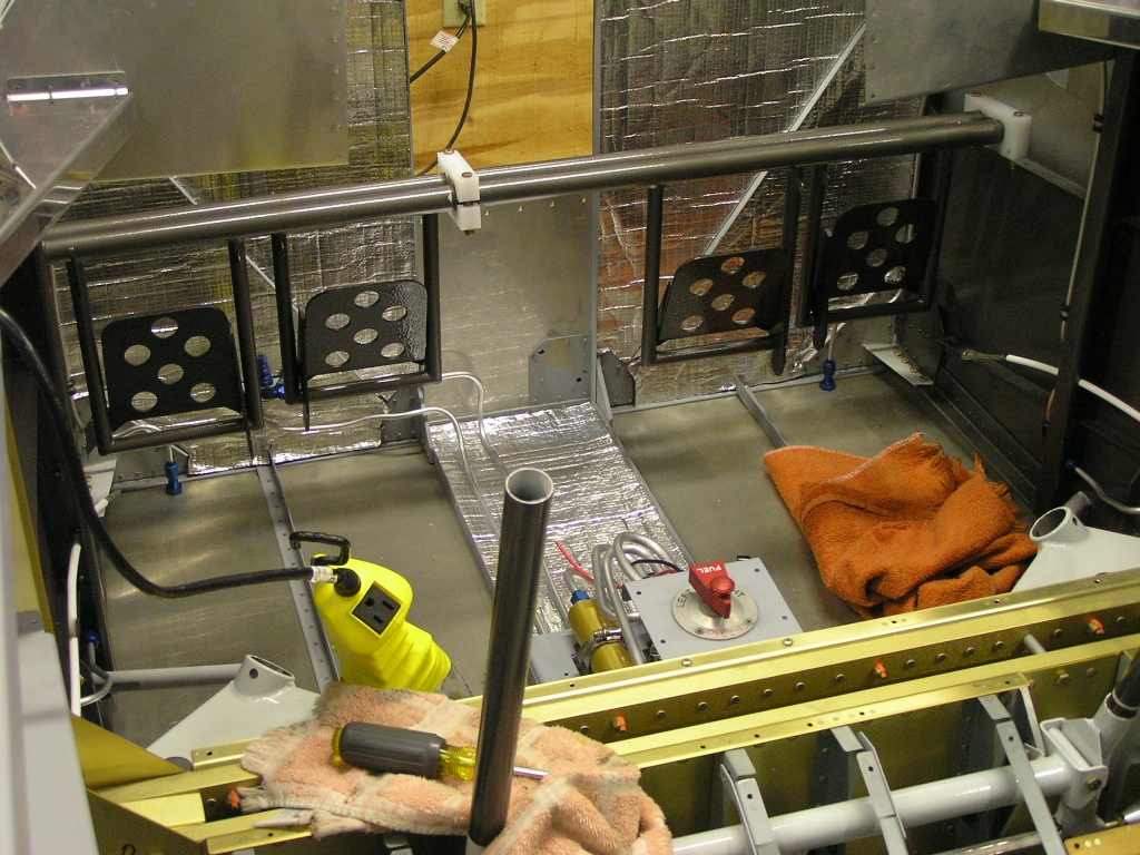 |
1.0 |
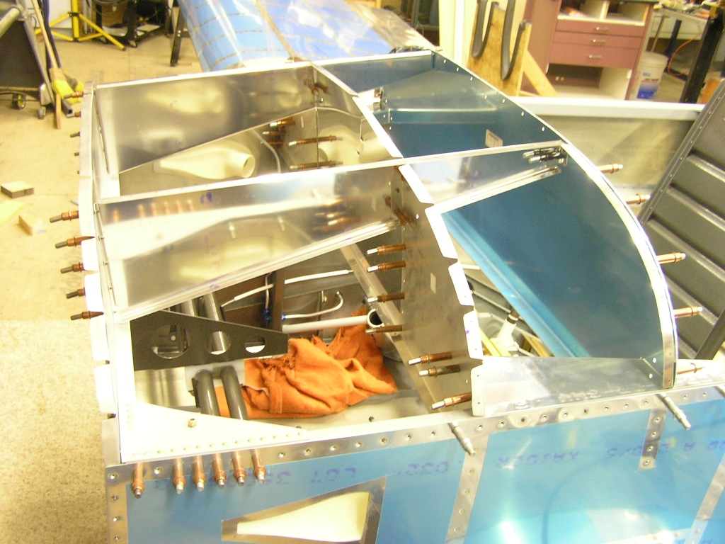
| 12/6/07 | Tonight I glued the NACA vents to the fuselage
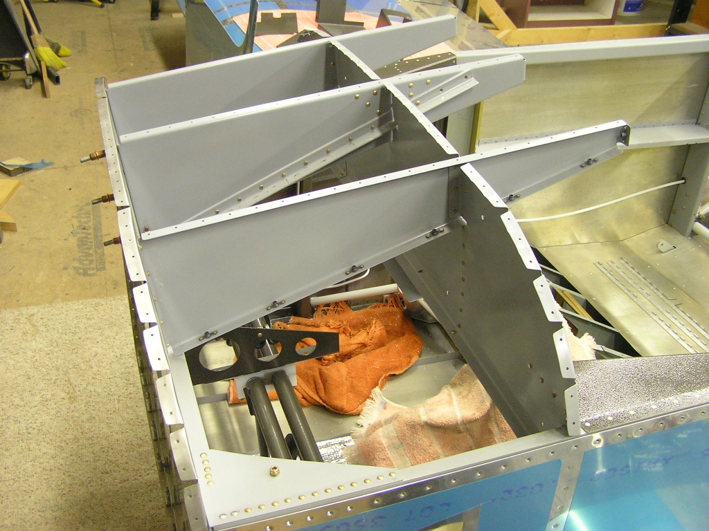
using E6000 epoxy.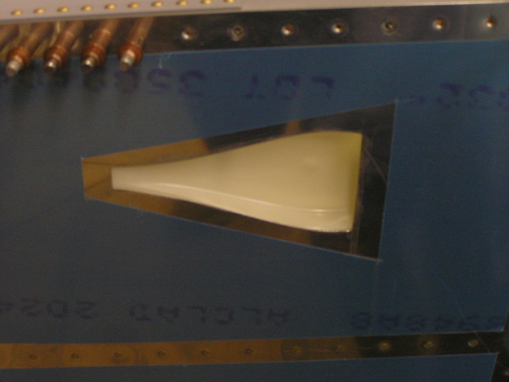 I clecoed the F-7107-L&R Forward Fuselage Ribs to the firewall. I
also clecoed the F-7105B-L&R Outboard Sub-panels as well as the
F-7105A Center Sub-panel. Since I will be hosting our
EAA Chapter 1211
Holiday Party at our home again this year, I went ahead and
clecoed the panel in for visual appeal. |
1.5 |
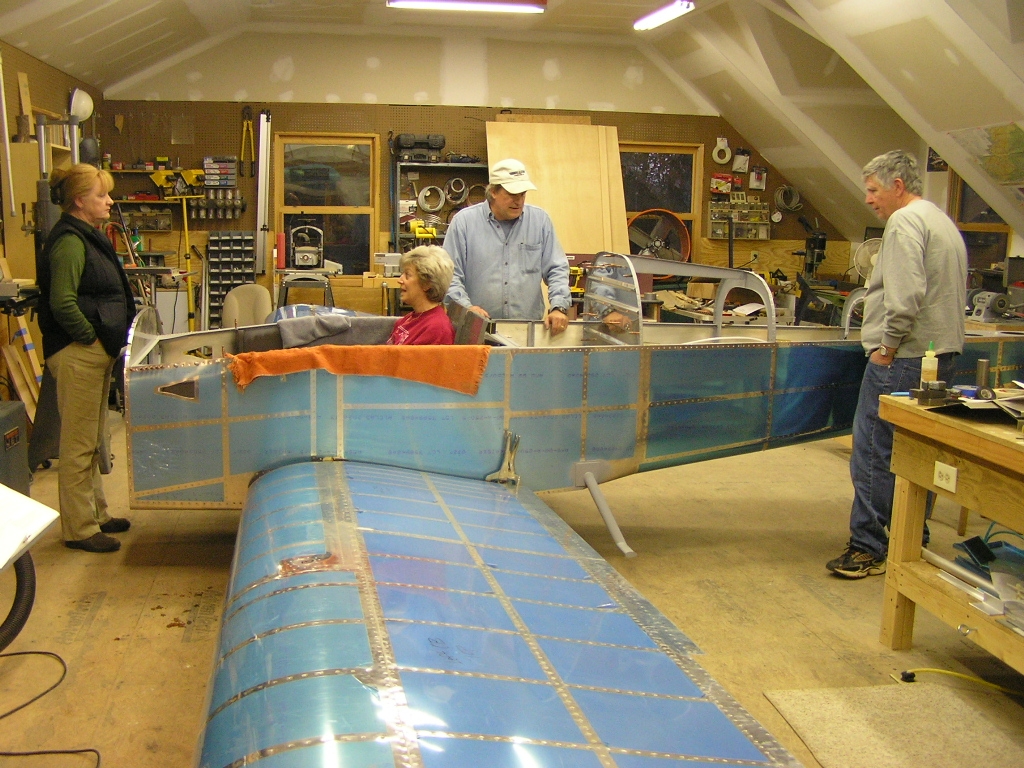
| 12/9/07 | We had a great EAA1211 Holiday Party here at
the house last night. After most of the guests left, I got
fellow EAAer and soldering master, Jack
Ryan, to solder leads on my micro-switches that will go
into my stick grips. After installing heat shrink on the switches I put them away and
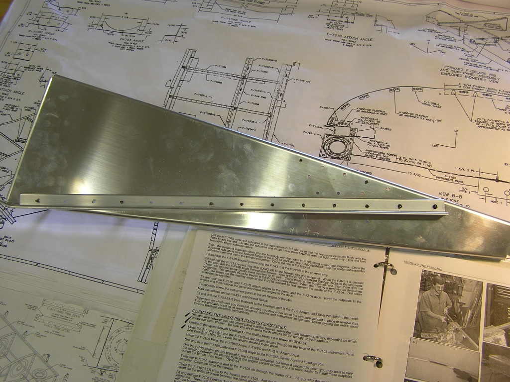
disassembled the forward fuselage assembly. I fabricated
the F-7108B angle as well as the F-7108C and F-721D attach
angles. I drilled and clecoed the F-7109 plate and F-7108B
angle to the F-7108A center forward fuselage rib then
disassembled and deburred. I then measured and drilled the F-746 engine control bracket
to the F-7105A subpanel and disassembled and deburred. I
decided now would be a good time to drill the F-721A Forward
canopy decks and deburr. I then countersunk for rivets. I deburred and scuffed the collection of parts and primed
with self-etch. |
4.5 |
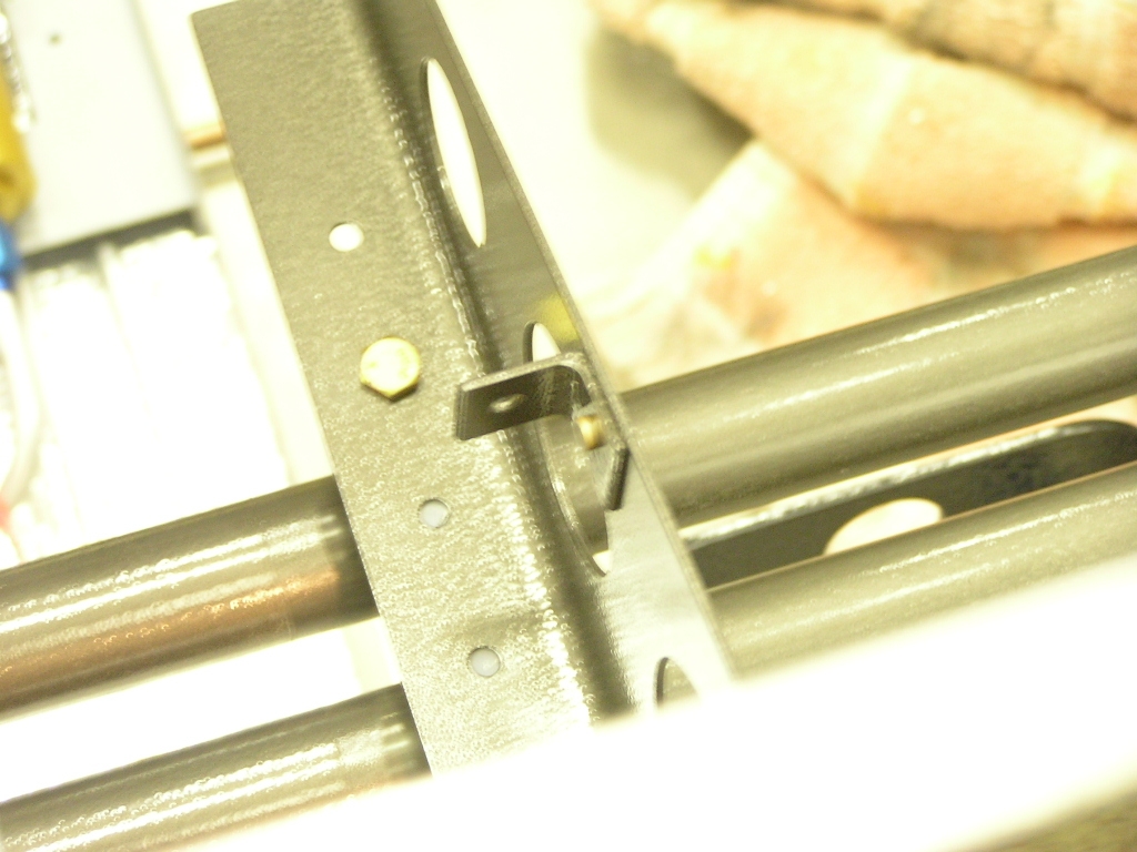
| 12/15/07 | I finished priming the forward fuselage ribs
and sealed with a clear SEM sealer called Chip Guard.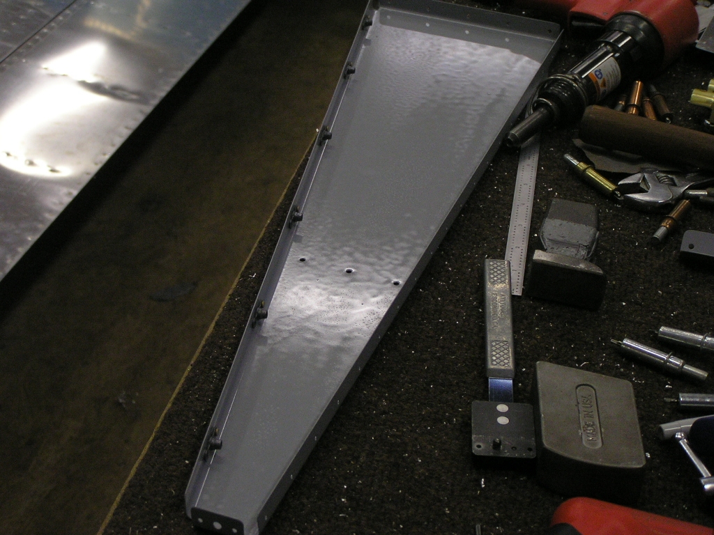
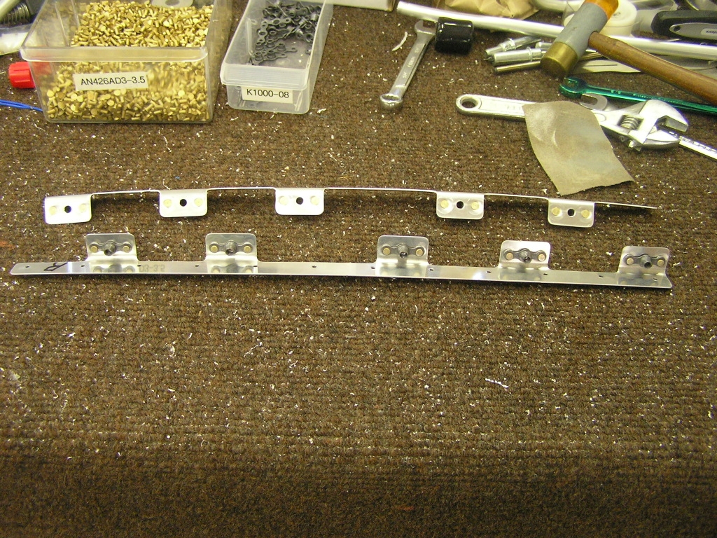
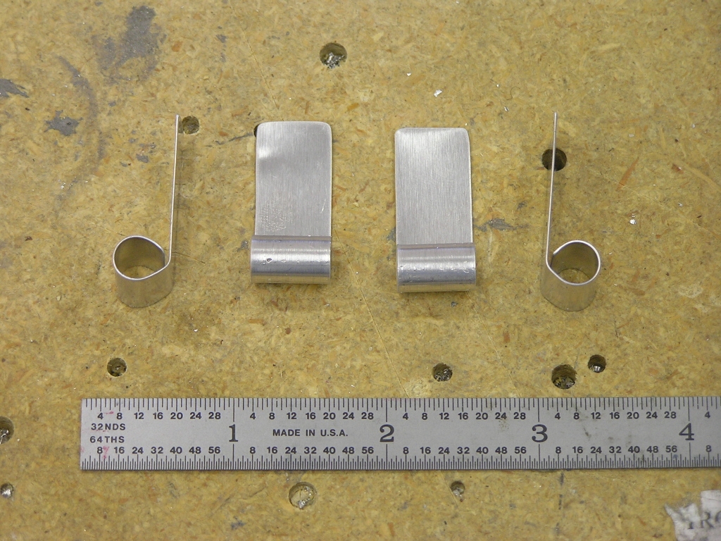
I fabricated a clip that I riveted to the center rudder pedal
support bracket. I will attach adel clamps to hold the
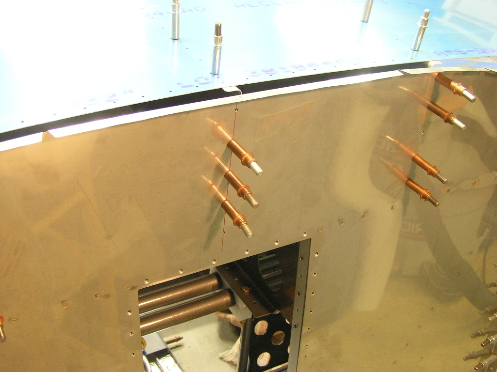
brake lines. I clecoed the F-7107-L&R forward fuselage ribs and then
clecoed the top skin on but left a gap in order to locate the
center rib for drilling to the firewall. After careful
measuring I drilled, deburred and dimpled the rib and the
firewall. Next, I clecoed the top skin to the forward fuselage and
match drilled. |
6.0 |
| 12/16/07 | I fitted and riveted the forward canopy covers.
The plans do not ever mention when to rivet these puppies but I
now wish I had waited to rivet the aft canopy decks. The
problem is that there is no way to use solid rivets to join them
together and in the aft-most rivet location after the aft decks
have been installed. Ok well, nothing a few pulled rivets
can't fix.
I re-installed the panel and drilled the F-721C&D attach angles
to the forward canopy decks. After removing the panel I
riveted the angles. With all the small tasks completed I riveted the forward
canopy section together permanently. The only thing I did
not rivet was the flange of the F-7108A center forward fuselage
rib to the firewall. After drilling the holes, I
discovered I had no way to dimple the firewall. I decided
to place an order with
Cleaveland Tools
for a #30 Pop Rivet Dimple Set.
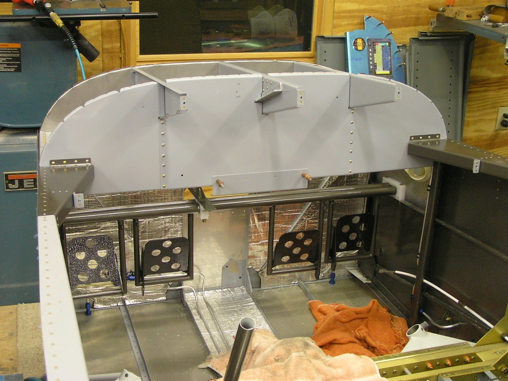
I have officially reached the end of the fuselage plans so
technically the structural (aluminum) construction phase is
over. I received notification that my finish kit will be
delivered sometime during the week of January 7th. All in
all, this is pretty good timing. I still have a number of
things yet to do to keep me busy until then. |
7.0 |
| 12/21/07 | Deburred and dimpled the forward canopy rib
flanges. I got the #30 Pop Rivet Dimple Set so I dimpled
the holes in the firewall for the center rib and then riveted
the rib. I measured and drilled the 2.0" hole for the
cabin heat inlet using a hole saw. 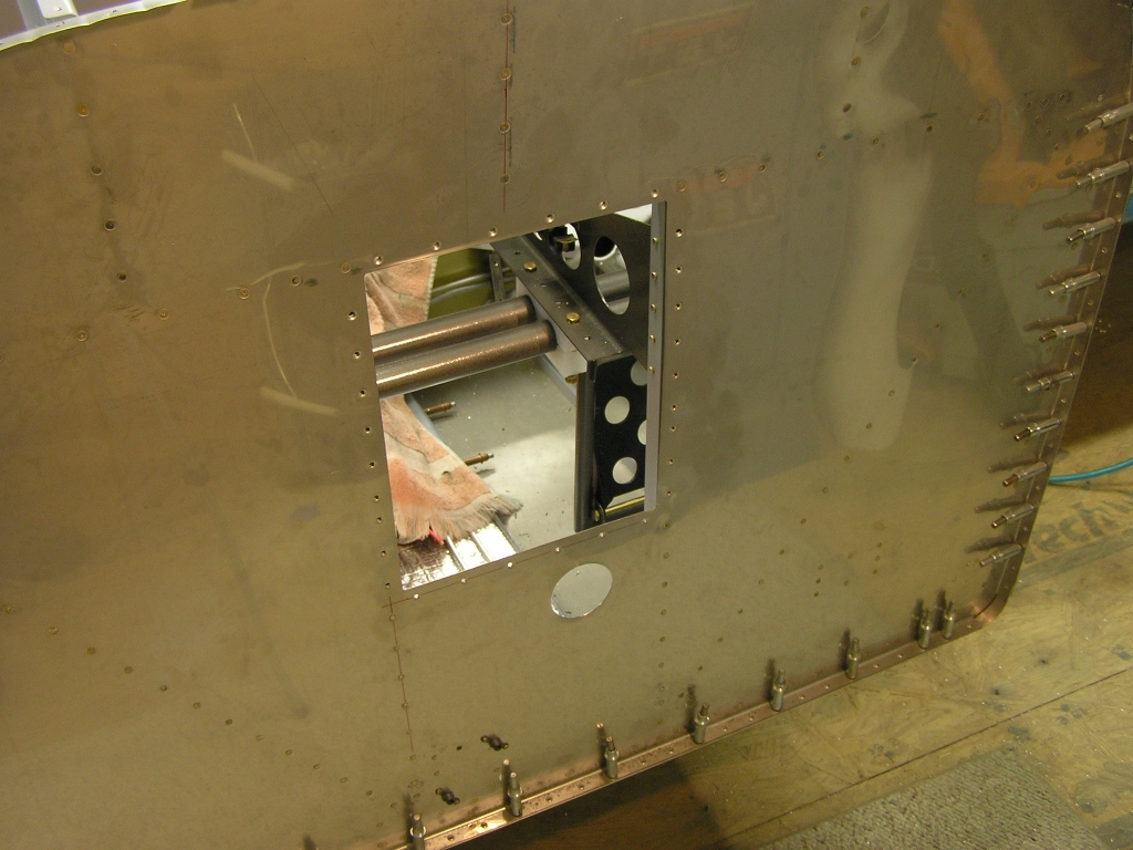 |
2.0 |
| 12/22/07 | I have not yet fabricated the small elevator
pushrod that connects the control column to the elevator
bellcrank. I went ahead and cut it to the length specified
in the plans and drilled and riveted the rod end bearings.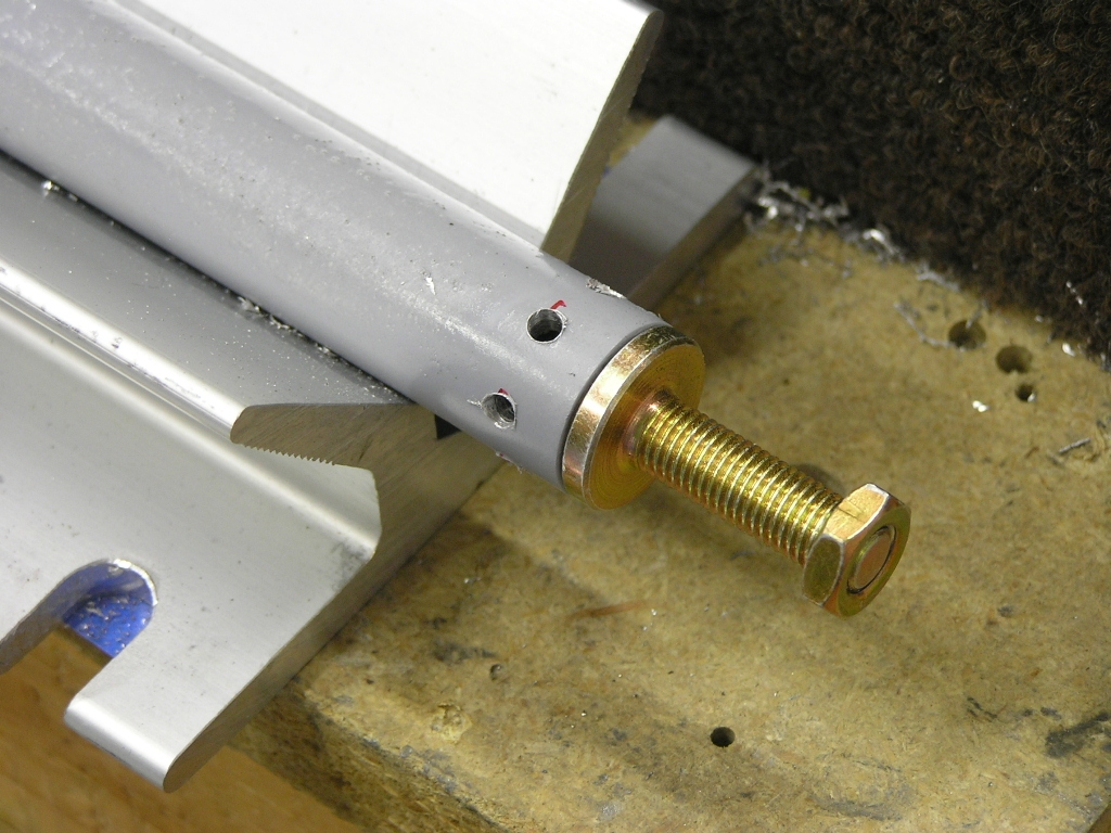 Aileron Trim Installation |
3.0 |
| 12/23/07 | I fabricated and installed the aileron trim
control as well as the Ray Allen servo. While not
difficult, the task did require me to crawl into and out of the
cabin about 10 times. 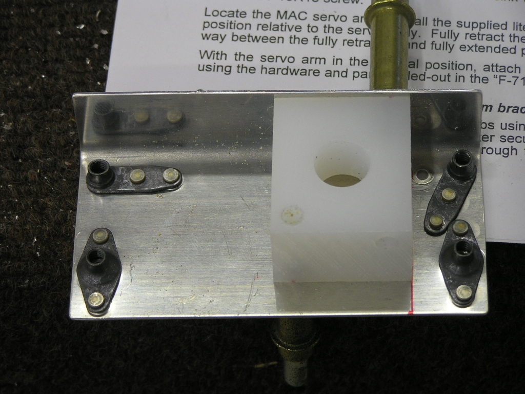 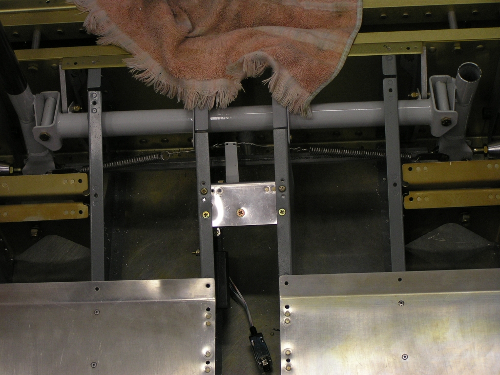 I went ahead and terminated the servo wires with a 9-pin D-sub male
connector. The wires used by RAC are 26 AWG so by doubling
up the stripped wire in the pins it is very secure. |
4.0 |
| 12/24/07 | Today I drilled and mounted the brake fluid
reservoir on the firewall. 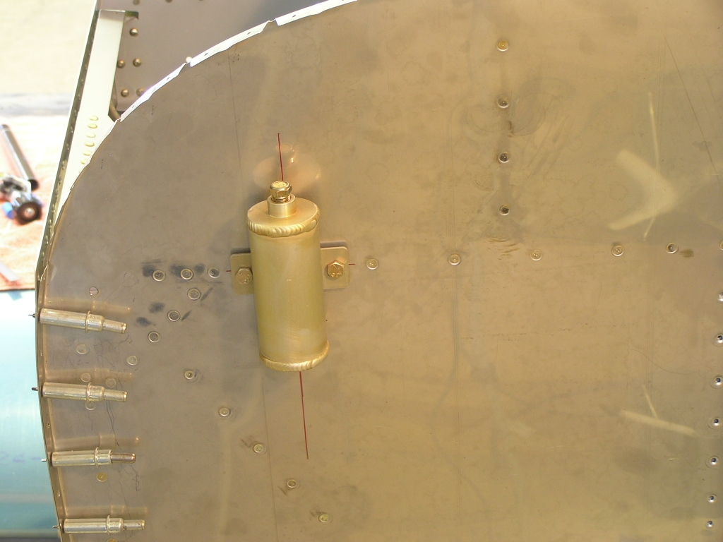 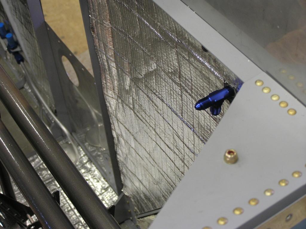
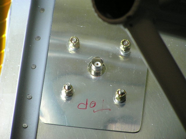
I also drilled and installed the transponder antenna on the
cabin floor in the right front corner next to the vent line
bulkhead. I also fabricated a few clips out of scrap .020 for securing
the static line along the longerons. |
3.0 |
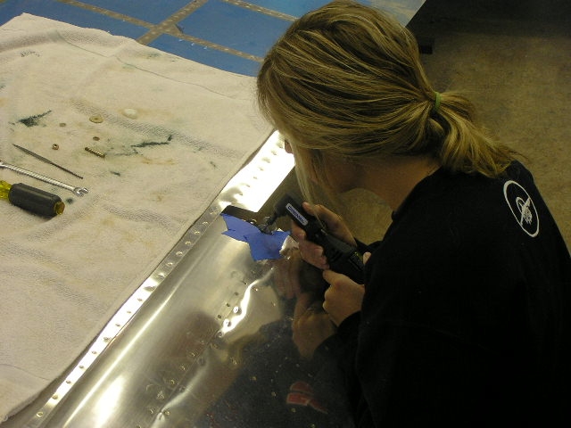
| 12/29/07 | My daughter, Carly,
is visiting for a few days so I put her to work. She is a
sophomore at Abilene Christian University. You can see
where she gets her "good looks" from...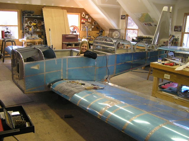 
We removed the flaps and ailerons. While we were at it I
ground down the screw that attaches the rod end to the aileron
and Carly used the Dremel to ground out a small notch in the top
skins. I fabricated a doubler plate for the Comant CI-122 COM
antenna and we drilled it to the fuselage belly under the gear
attachment bracket just forward of the spar bulkhead. This
places the COM antenna exactly 36" from the transponder antenna. I also started fabricating the magnetometer bracket to attach
to the upper F-907 bulkhead. |
4.0 |
| 12/30/07 | Finished mounting and drilling the attach
bracket for the magnetometer. Cleaned up the shop a little
and set up to deburr and dimple the forward top skin. |
1.0 |
| 1/1/08 | Happy New Year! Today I finished
deburring and dimpling the three fuselage top skins. I
also removed the rudder and drilled the lower fiberglass bottom
fairing on. |
4.0 |
| Removed Wings | ||
| 1/12/08 | Today I had some help from fellow EAAers
Jim Olson,
Bill Smith and Jack Ryan to
help me remove my wings. The whole process took only 10
minutes and while he was here, I had Jack solder some leads on a
micro switch for me. All it cost was lunch. Good
deal. Next, I removed the vertical stabilizer, elevators and horizontal stabilizer. I spent the rest of the evening cleaning up and deburring holes. I got confirmation that my
Finishing Kit was shipped and should arrive late next week. |
3.0 |
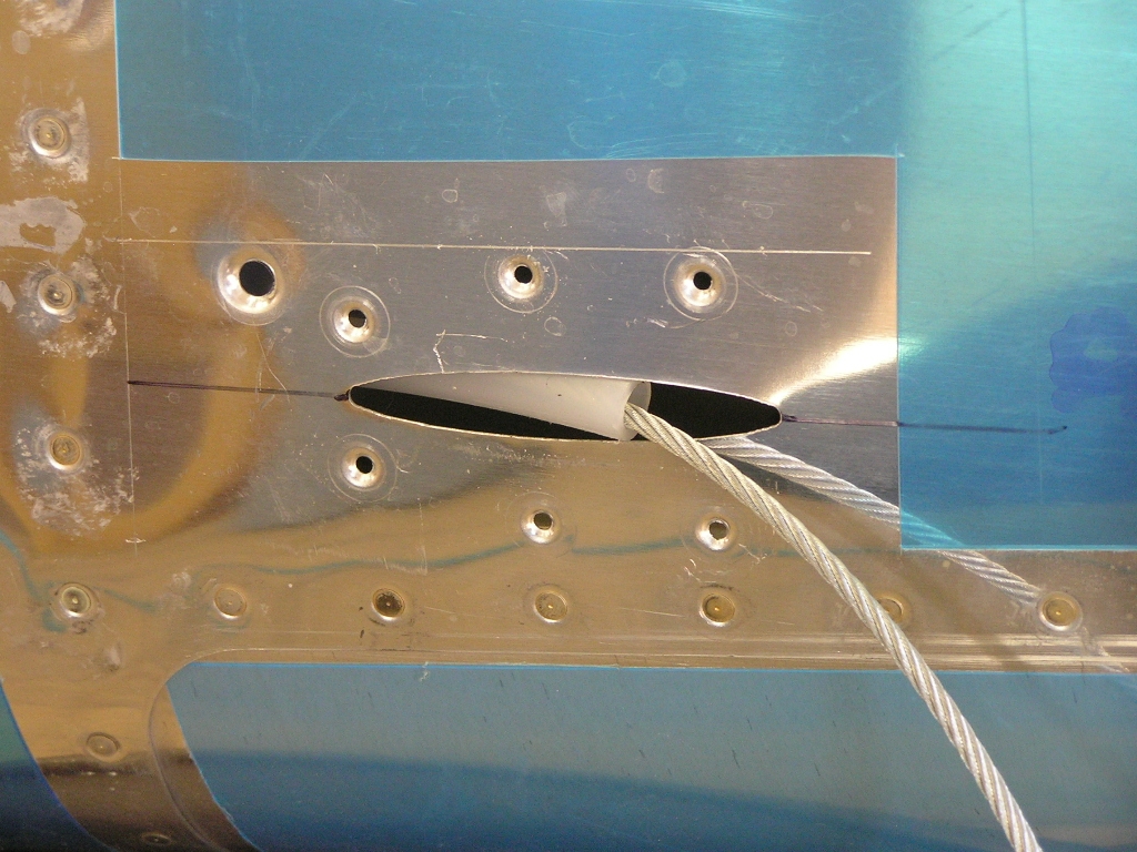
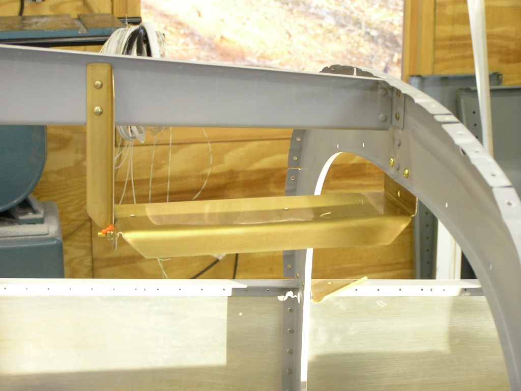
| 1/13/08 | Today I removed the flap motor housing in order
to paint and also removed the baggage bulkhead. I
installed a few odd rivets that I had not installed. I
also riveted the rudder cable fairing I got from
Avery Tools. I also installed
the adel clamp securing the cable guide.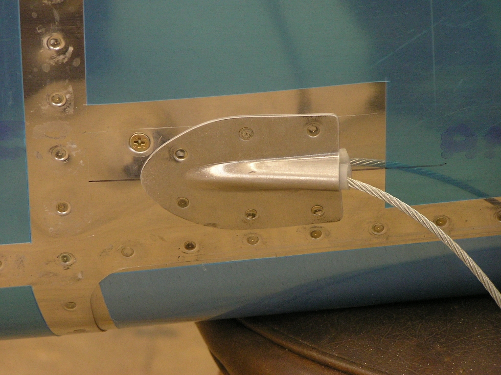
I had previously bought some brass screws, washers and nuts at
Lowes so I went ahead and installed the magnetometer bracket. She looks a little naked now... |
3.0 |
| 1/18/08 | My Finishing Kit arrived today so after
unloading, Lynne and I inventoried it and can report that I only
had one item missing... Lynne really liked the pink cowl.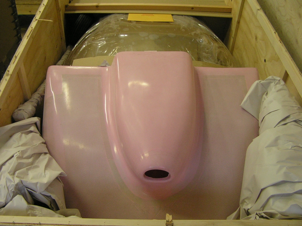 |
2.0 |
| 1/19/08 | I recently received the cool throttle quadrant
I ordered from Aircraft Spruce.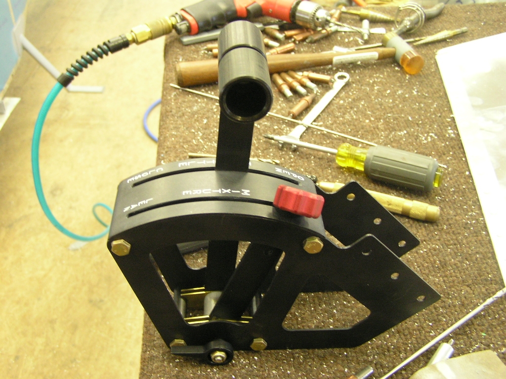 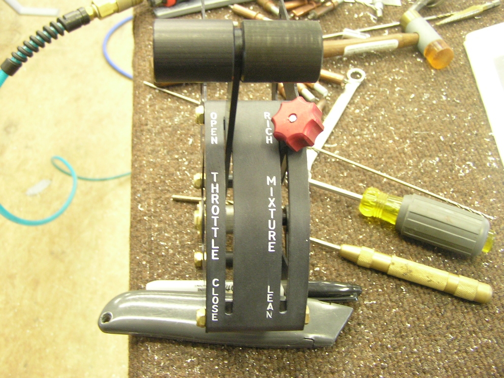
Today I just knocked a dozen or so small tasks such as drilling
wiring access holes in the fuselage for the wing wiring. I
also finished storing the various parts in the finishing kit. |
3.0 |
| 4/7/08 |
Installing Cabin-Side Brake
Lines I finally got around to installing the brake
master cylinders and the custom hoses I bought from Brett at
Bonaco. I am really impressed with
how well they fit and the look with the smoked covering. |
1.0 |
| 4/13/08 | I decided to go ahead and install the F-704K
upright cap strips since I could see no reason for holding off.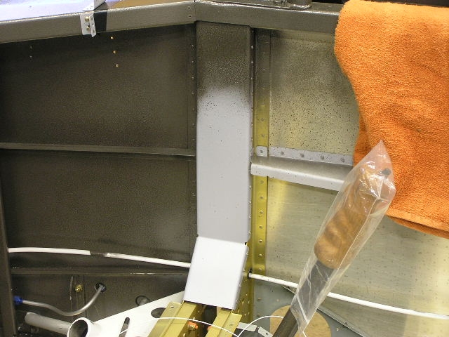 |
3.0 |
|
Total Hours this Page |
||
|
Total Hours Fuselage (as of 4/13/08) |
||
| Next: Fuselage 6 |


Copyright ©2005-08
Hosted by NTI Networks